Balancing flow across a manifold.
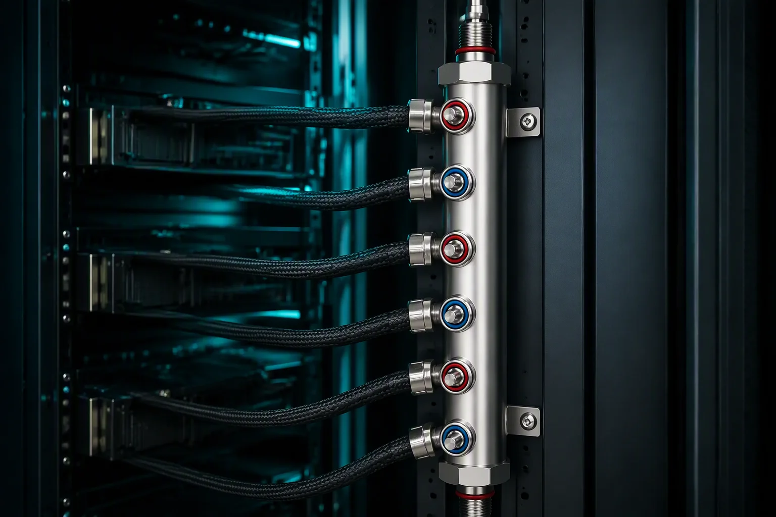
A manifold does not deliver flow evenly because it was machined well; it delivers flow evenly because the branches are hydraulically similar, or because someone trimmed them. This brief covers how flow actually divides in a parallel bank, which device belongs in a branch, the Cv arithmetic behind a restrictor, four ways to measure what you got, and a field procedure for fixing a loop that is already installed and already uneven.
DL-005 · Published 2026-09-06 · 8 min read
Rack-level flow planning starts from a baseline: 1.2 L/min per kW of heat load. An 80 kW rack therefore moves roughly 96 L/min — about 25 GPM — which at a typical single-server feed of about 12 L/min works out to eight server branches sharing one manifold pair. Eight parallel paths, one supply header, and a simple rule that decides everything: the flow each branch gets is set by its own resistance relative to the others, not by the order the drawing lists it in.
Hydraulically, that means small resistance differences produce proportional flow differences. A branch with 20% more resistance gets about 10% less flow, and a branch that loses flow loses thermal margin at exactly the moment the rack is at full load. Balance is a thermal control, not a plumbing nicety.
Why imbalance is a thermal problem.
In a parallel bank, every branch sees the same pressure difference between supply and return. Flow then divides in proportion to conductance, and conductance is the inverse of resistance.
Take a branch planned at 12 L/min carrying 15 kW through a 25% propylene glycol mix — roughly 1020 kg/m³ and 3900 J/kg·K. At design flow the plate sees a rise near 18.9 K. Let the same branch fall to 10 L/min because a neighbouring branch is taking more than its share, and the rise at the same heat load goes to about 22.6 K. Nothing leaked, nothing failed, no alarm sounded: the junction temperature simply moved 3.8 K closer to the limit, and the tray now throttles earlier than the thermal design said it would.
Two effects drive the imbalance. The first is header friction: coolant entering the supply bank loses pressure as it travels, so the port nearest the inlet sees a slightly larger supply-to-return difference than the port at the far end and takes more flow. The second is branch resistance: different cold-plate designs, different hose lengths, an extra elbow, a longer return path. Manifold machining helps with the first part — our banks are cut so each port presents the same effective area — but it cannot make two different cold plates behave like one.
- 1.2 L/min/kW — rack flow planning basis: 80 kW ≈ 96 L/min ≈ 25 GPM
- ≈ 12 L/min — typical single-server branch, about eight per 80 kW rack
- 18.9 K → 22.6 K — rise on a 15 kW branch when flow falls from 12 to 10 L/min
- < 1/40 — the LBNL ceiling on manifold supply plus return pressure drop
What to put in the branch.
Four devices do the job, and they sit on a straight trade between how precisely they hold a setpoint and how much they cost to install and maintain.
| Device | How it sets flow | Adjustable | Best used when |
|---|---|---|---|
| Port symmetry, no device | equal port areas and equal branch resistance | no | identical plates, equal hose runs, a bank that balances itself |
| Fixed restrictor / orifice | a drilled or swaged bore with a known Cv | no — changed by swapping the insert | the imbalance is known at design time and never moves |
| Manual balancing valve | a setting locked after commissioning | yes, at commissioning | mixed plate types, retrofit loops, trays that will be re-populated |
| Pressure-independent control valve | an internal regulator holds flow across pressure swings | setpoint, not a position | loops where other branches switch on and off and the header pressure moves |
Two practical constraints decide between them. First, every device here is a deliberate pressure loss, and pressure loss is pump head — the manifold stays passive under the 1/40 budget while the trim device spends head on purpose. Second, a device that has to sit nearly closed to hit its target is untunable: a small turn becomes a large flow change, and nobody can repeat the setting six months later. If the arithmetic says the valve runs below roughly a tenth of its travel, the trim is being done by the wrong device — change the orifice size, not the valve position.
A pressure-independent valve earns its cost only when the pressure it is regulating against actually moves. In a rack where all eight trays run continuously, the header pressure is stable and a locked manual setting holds. In a rack where trays are powered down individually and the CDU holds a fixed differential pressure, the surviving branches see more pressure each time one drops out — and that is the case where a flow-regulating device pays for itself.
Cv arithmetic for the branch you are trimming.
One formula covers restrictors, balancing valves and couplings alike: Q = Cv × √(ΔP / SG), with Q in GPM, ΔP in psi and SG the specific gravity of the mix.
Work it in the direction the loop asks for. If you need to trim — deliberately lose pressure in a branch that is running rich — pick the ΔP you want to create and solve for Cv. To pass 1.7 GPM at a 0.5 psi trim with a 25% propylene glycol mix at SG 1.03, Cv comes out near 2.4. To create a 2 psi trim at the same flow, Cv is close to 1.2. That second figure is worth remembering, because it is also the published Cv of a UQDB04 blind-mate class part: a dash-04 coupling running at its 1.7 GPM rated flow drops about 1.9 psi with water, and about 2 psi on the glycol mix.
The same formula tells you what a device costs when you are not trying to trim at all. A full-server branch at 3.17 GPM passes a dash-08 coupling — Cv floor 2.50 — at about 1.66 psi on the glycol mix. Put the same branch through a dash-06 part at its 1.60 Cv floor and the drop rises to about 4 psi, before you have counted the hose. This is why class selection comes before trim: pick the coupling from the flow table, then decide whether the residual imbalance needs a device at all.
- Cv 2.4 — passes 1.7 GPM across a 0.5 psi trim at SG 1.03
- Cv 1.2 — passes 1.7 GPM across a 2 psi trim — the UQDB04 class value
- 1.66 psi — drop across a dash-08 coupling at 3.17 GPM, Cv 2.50, SG 1.03
- ≈ 4 psi — the same branch squeezed through a dash-06 Cv 1.60 floor
Measuring flow without breaking the loop.
You cannot balance what you cannot measure, and the measurement you choose decides how much of a maintenance window the job takes.
| Method | Typical accuracy | Wetted parts | Practical note |
|---|---|---|---|
| Inline turbine or impeller meter | ±1–2% of reading | yes | needs a straight run upstream and downstream; adds its own small ΔP |
| Ultrasonic clamp-on | ±2–5% of reading | no | nothing enters the loop; needs a known wall thickness and a clean, full pipe |
| Differential pressure across a known restriction | depends on the restriction's calibration | yes | the cheapest permanent option if the branch already has a characterised orifice |
| Heat balance (ΔT across a known load) | limited by the temperature measurement | no extra | uses sensors many racks already carry; error amplifies as ΔT shrinks |
The heat-balance route deserves the arithmetic, because it is the method most often attempted with the least margin. Flow equals power divided by density, specific heat and temperature rise. For a 5 kW cold plate showing a 5 K rise on a 25% glycol mix: 5000 ÷ (1020 × 3900 × 5) = 2.51×10⁻⁴ m³/s, or about 15 L/min. That figure is above the 1.2 L/min/kW planning baseline, which is what you would expect if the loop was commissioned with margin — the method reports the flow you actually have, not the flow on the drawing.
The catch is error propagation. A 0.5 K error on a 5 K rise is a 10% flow error; a 1 K error is 20%. Use a matched pair of calibrated sensors, read them at the same instant, and treat any result within ±15% as "in the band" rather than as a precise number. For commissioning records, pair the heat balance with one clamp-on meter reading on the branch you care most about.
Correcting imbalance in an existing loop.
Six steps, in this order. The sequence matters more than the tools: trimming valves before you have eliminated mechanical causes locks a fault into the commissioning record.
Commissioning sequence
When trimming is the wrong answer.
A valve can hide a fault as easily as it can fix a distribution problem, and a hidden fault reappears as a different symptom.
A restriction that should not be there
If one branch is short and the others are fine, the odds strongly favour a local fault: a hose with an internal flap from a bad cut, a swaged fitting with a partial obstruction, a coupling that was never fully seated and is throttling through a half-open valve. Trimming a neighbour to compensate raises the header pressure the faulty branch sees, so the fault looks cured at commissioning and reappears when a tray is swapped.
A design margin being spent
Trimming is not free. Every restrictor and valve you add is pressure the pump must supply, and on a rack with an 18 psi total budget the trim stack competes with the 1/40 manifold allowance and with the cold plates that take roughly 56% of the rack's pressure drop. If balancing requires more than a few psi of trim across the bank, the better fix is usually upstream: a larger supply bore on the heavily loaded leg, or a port map that feeds the far trays from a second inlet. Published manifold platforms span DN03 to DN10 for exactly this reason.
A loop that will change next quarter
Balancing settings belong to a configuration. If trays are going to be added, moved or replaced with a different plate generation, the settings are a snapshot and the next engineer will inherit numbers that no longer apply. In that case pick a device that can be re-set in place, and attach the baseline to the rack documentation where the next person will find it rather than to the commissioning engineer's laptop.
Three questions this brief answers most.
Do I need balancing valves on a rack manifold?
How do I size a balancing orifice with Cv?
How do I measure branch flow without a flow meter?
Send the port map. We will quote the bank that feeds it.
Configurable port maps, native UQD and UQDB ports, red-hot and blue-cool coding, 100% pressure tested per batch with the report in the carton. Quoted within 48 hours, MOQ from 50 pieces.