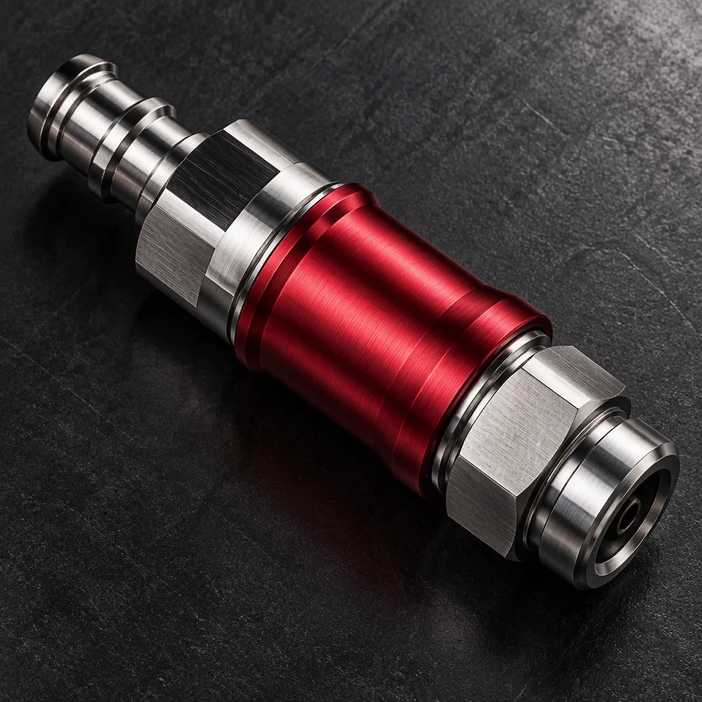

UQDB blind-mate couplings — docking for cold plates
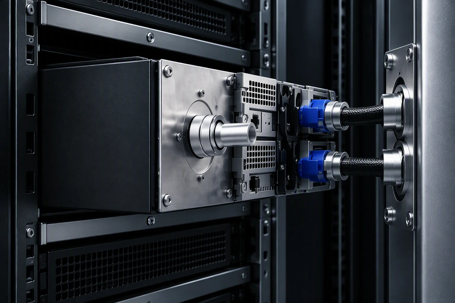
The plug rides on the server cold plate, the socket sits on the tray and backplate, and the tray self-aligns as it slides home.
Three values above: per the OCP UQDB specification
Request docking reviewBlind mating is a tolerance question, not a looks question.
Whether a tray docks without a hand on it depends on how much misalignment the design allows, and on what absorbs it.
UQDB and UQD are governed by two separate specification documents. A complete loop reads both: per the OCP UQDB specification, per the OCP UQD specification.

Port density and pitch
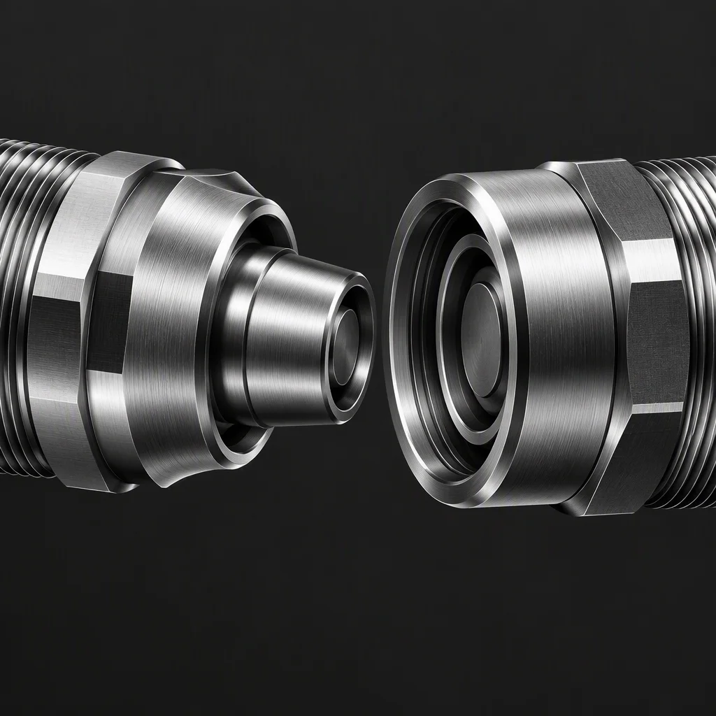
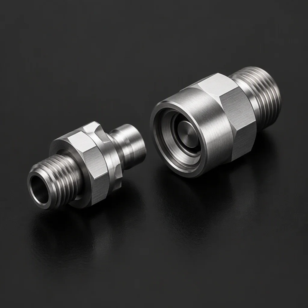
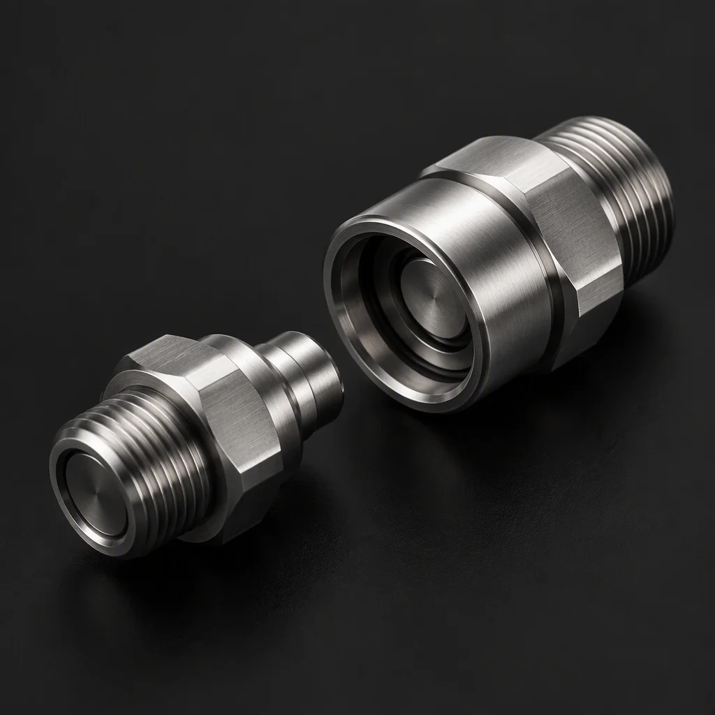
Three bores · one envelope · per the OCP UQDB specification
At the preferred pitch, a tray face takes a full port row the layout can be frozen against. Confirm the pitch before the tray drawing is released; a pitch decided afterwards moves the whole row.
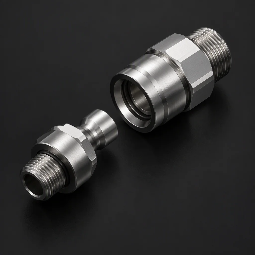
Port pitch, preferred · 20 mm
Plug width, maximum · 18 mm
Both values: per the OCP UQDB specification
Misalignment and what floats
The centre of this page · per the OCP UQDB specification
- MIS-A radial
- 0.5–1.0 mm
- MIS-A angular
- 0.5°
- Float absorbs
- ±1.0 mm
Two lines, two jobs. The first pair is what the design is allowed to be off by; the second is what the floating interface takes out before the seal faces ever touch. Set them as one budget, not two independent numbers.
Discussed: radial floor · angular window · float travel · seal seat left out of the budget
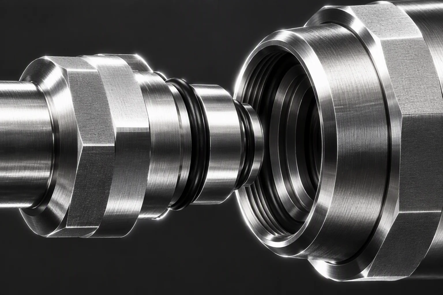
Without the float, the first docking pass grinds the seal faces; the leak then appears at the seat rather than at the coupling body, which is why the float is a life item and not a convenience.
The cold plate side
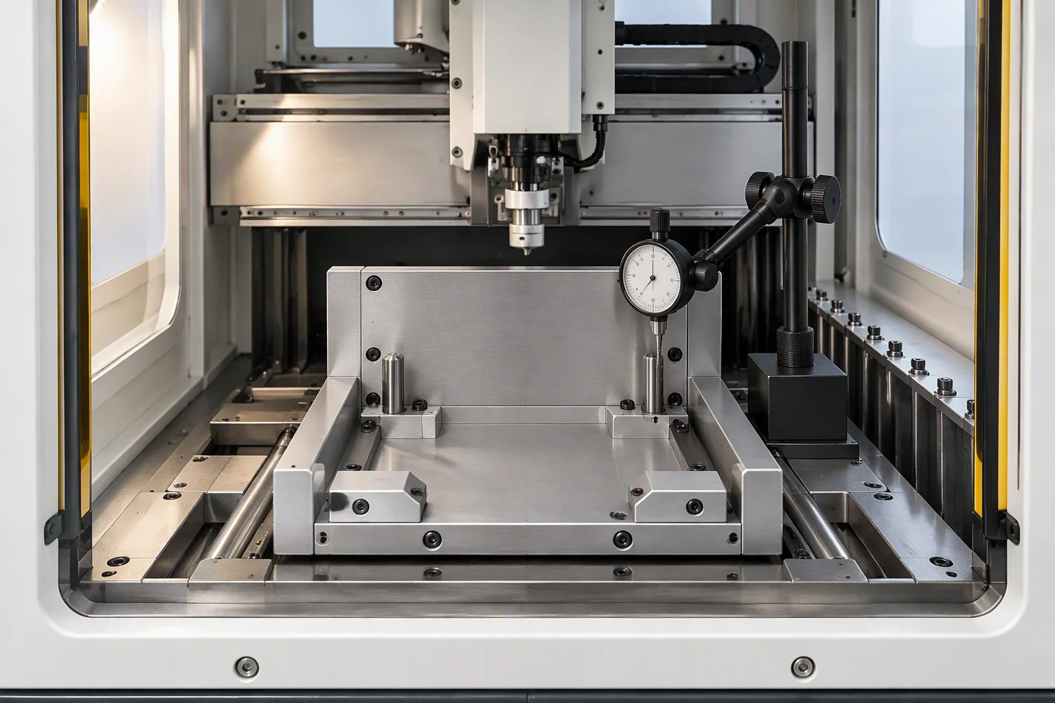
Face materials and flatness · per the OCP UQDB specification
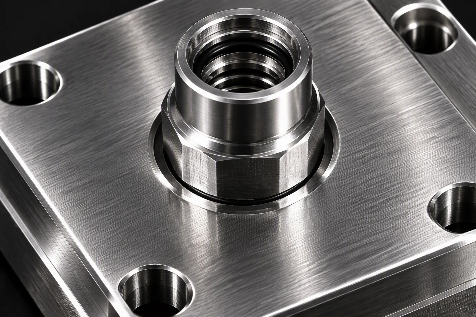
Material choice is a thermal and cost decision; the face flatness is the interface condition. Both are stated by the specification, not by DryLink.
Blind-mate states, in the rack
Float interface · socket row · docked position
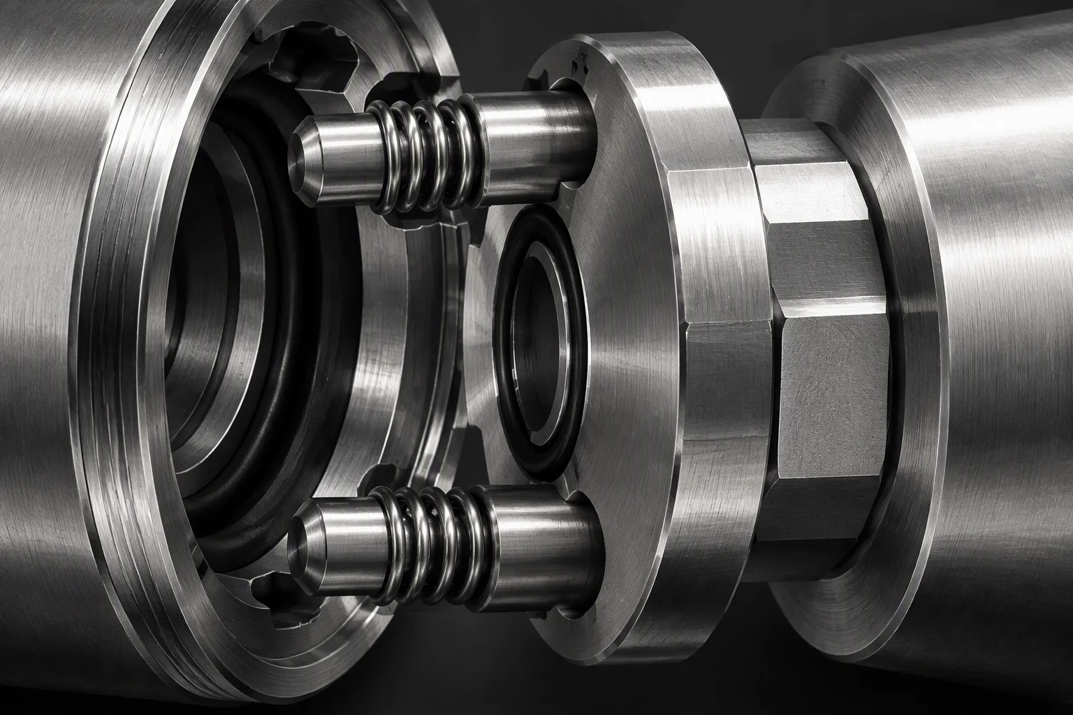
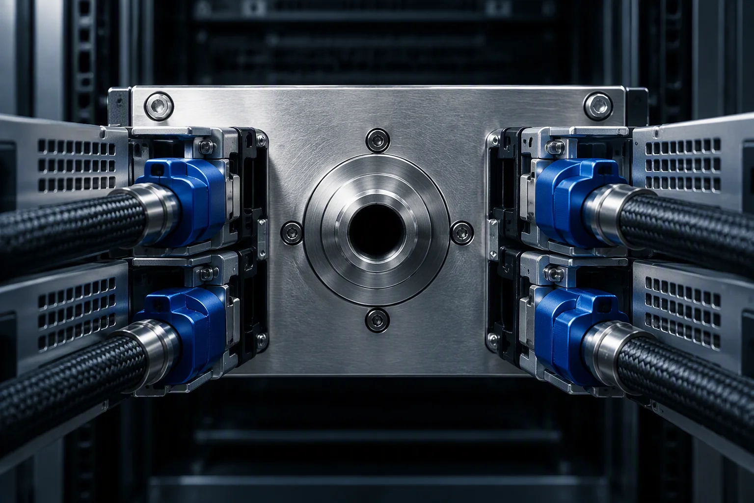

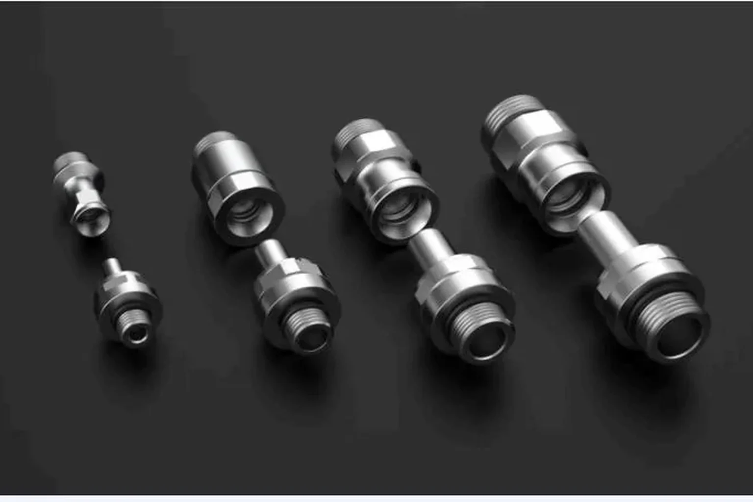
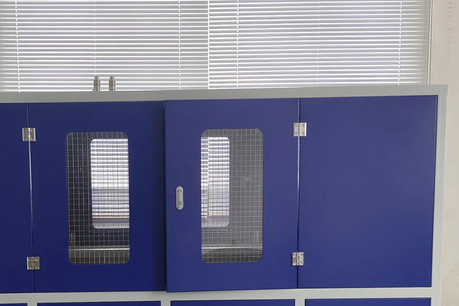
The manifold side of the interface
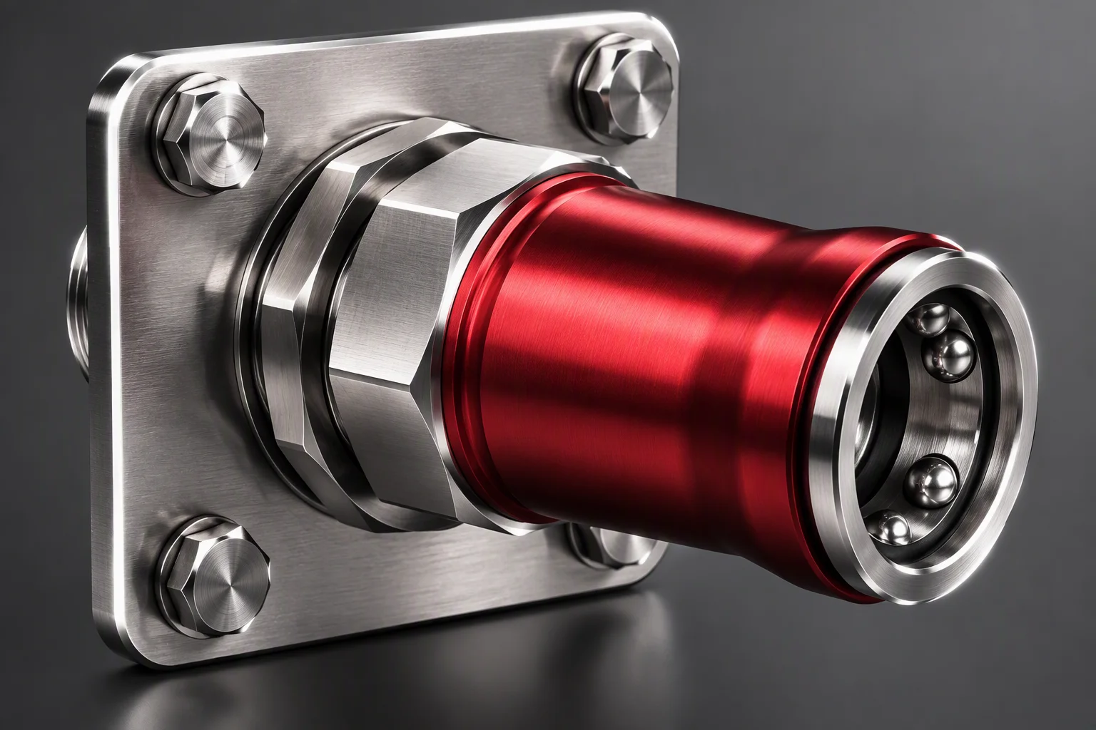
Socket row, seen square-on · same three envelope values
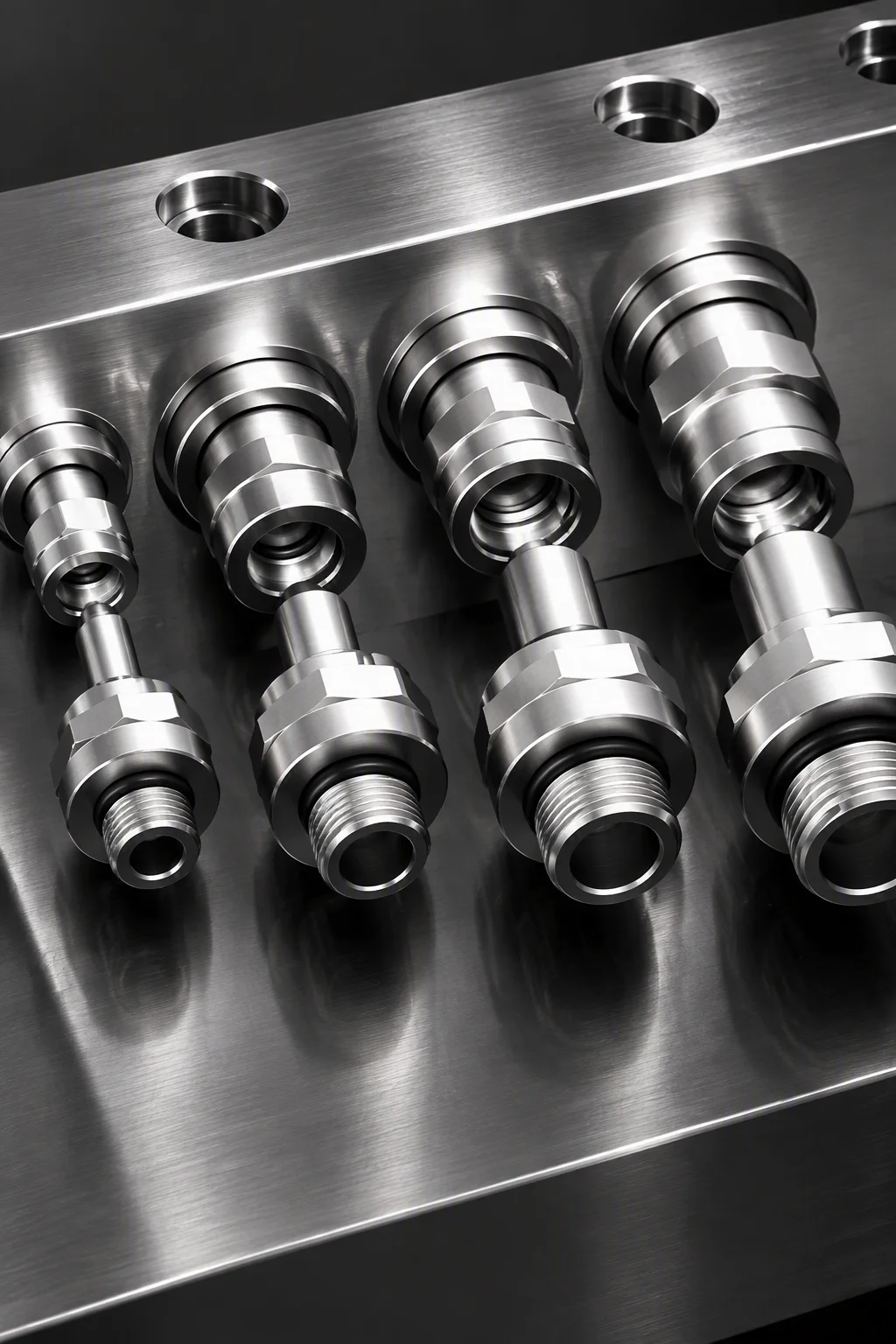
The tray side carries the plug, the rack side carries the socket row: the same envelope has to hold on both.
Docking force against the stack
Recommended values · per the OCP UQDB specification
Insertion force is the end of the tolerance chain, not a separate spec: the tighter the float absorbs, the larger the force the tray carries. Verify latch and rail loads in the stack, before the tray layout is frozen.
Testing references
Four standards · mapped one by one in the test plan
The four numbers above are testing references, cited so the review package can be checked line by line. The test plan maps each one to a station and a record; the one-page spec sheet travels with the quote.
Request the per-standard test plan
Send the tray drawings.
Tray face and backplate, plus the port count per tray. The answer is a docking tolerance review against MIS-A and the float travel.
Request docking reviewOne business day · English quote + one-page spec sheet · designed to the OCP UQDB specification