DryLink UQD & UQDB quick disconnects · rack manifolds
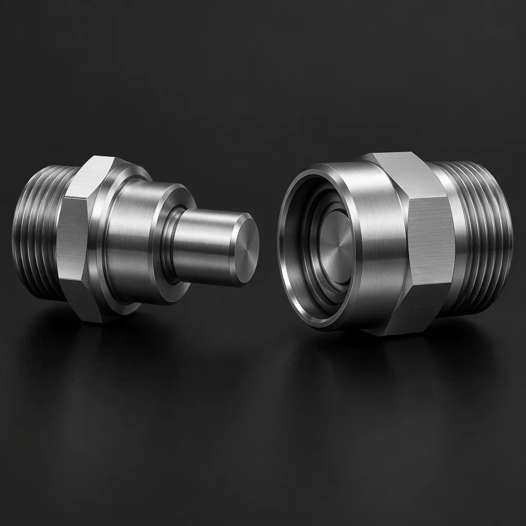
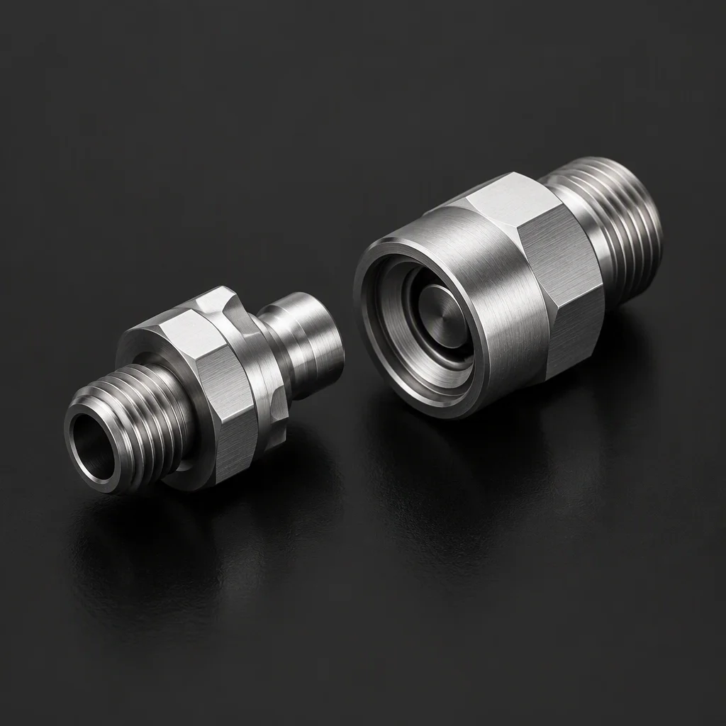
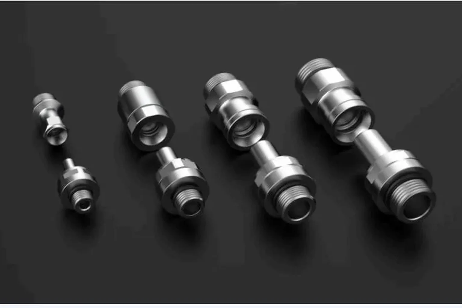
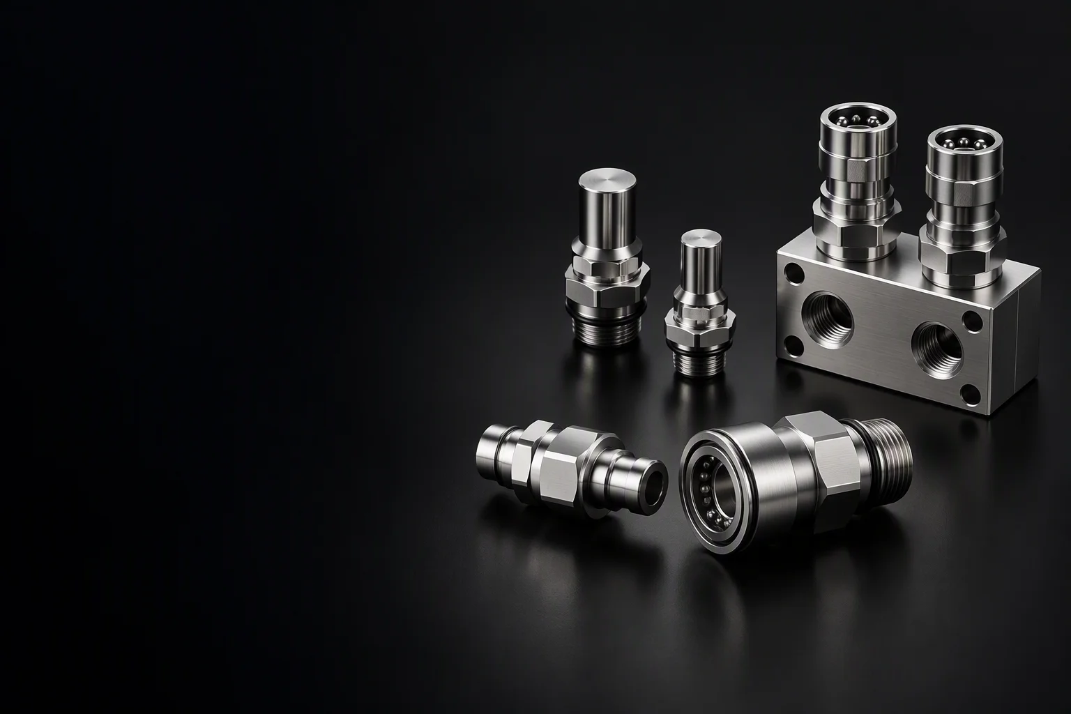
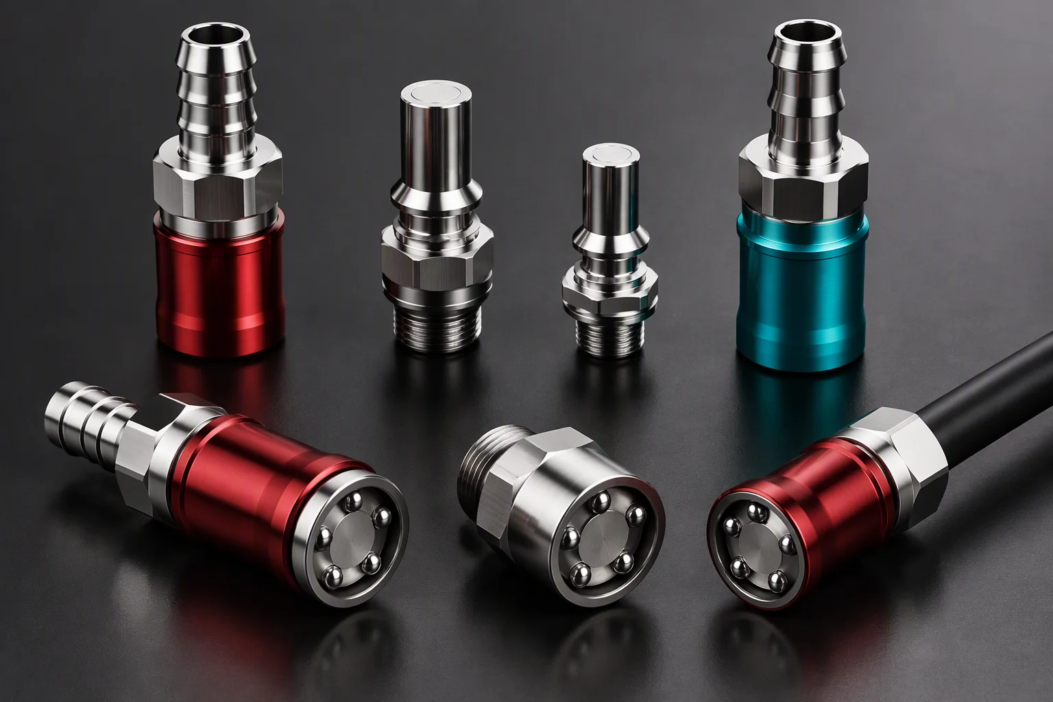
Three product groups on a dark workbench — hand-connect couplings, blind-mate pairs and a manifold section, held to the right with the left of the frame kept clear (generated image)

Three lines · one loop

Products — UQD Couplings,
UQDB Blind-Mate & Rack Manifolds

A hand-connect line, a blind-mate line and the rack manifolds they plug into. One part-number system, one test regime, one shipment — so the whole loop can be sourced in one place.

Request spec sheet
Bores · UQD 1/8"–1/2"UQD02–08 · per OCP UQD specification
Bores · UQDB UQDB03–06UQDB03/04/06 · per OCP UQDB specification
Ports per rack 42–52industry-published benchmark

Three lines, one ledger

Scope per line · every figure carries its level

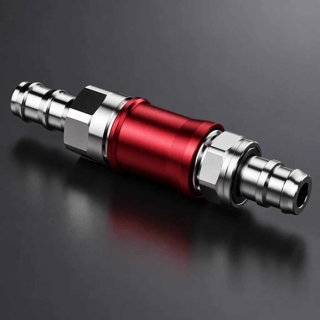
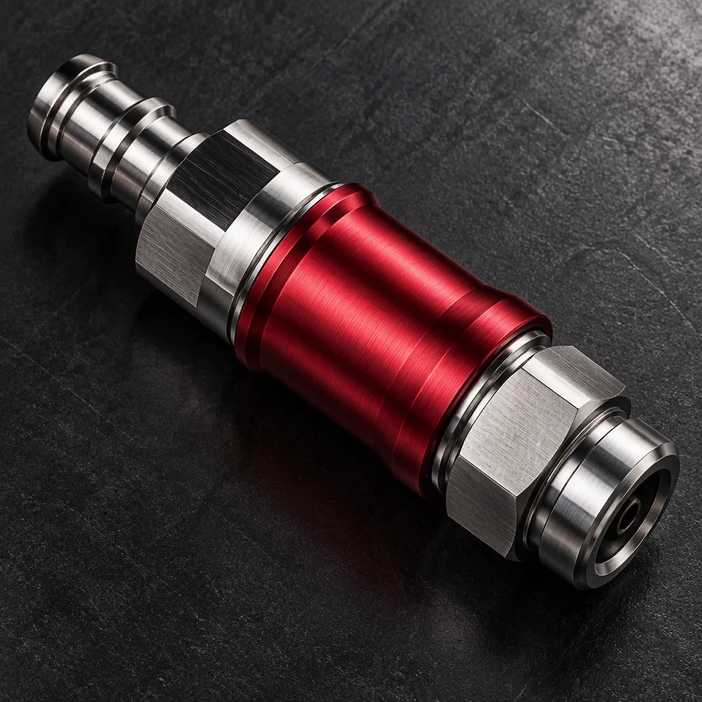
One hand-connect coupling pair, plug and socket joined, filling the frame (generated image)

UQD · hand-connect couplings

1/8", 1/4", 3/8", 1/2" — UQD02, UQD04, UQD06, UQD08; dry-break on connect and disconnect. Bore sizes and the dry-break requirement are specification values (per OCP UQD specification).

UQD line
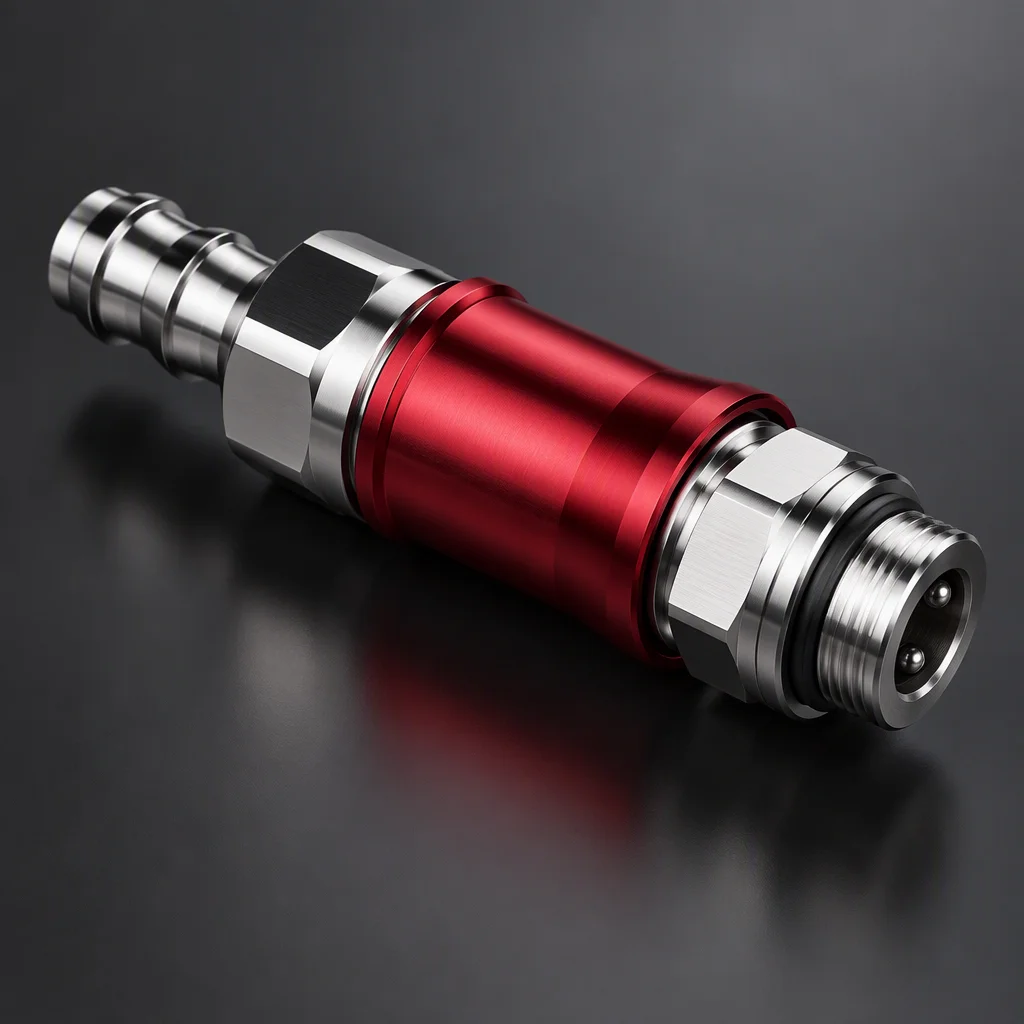
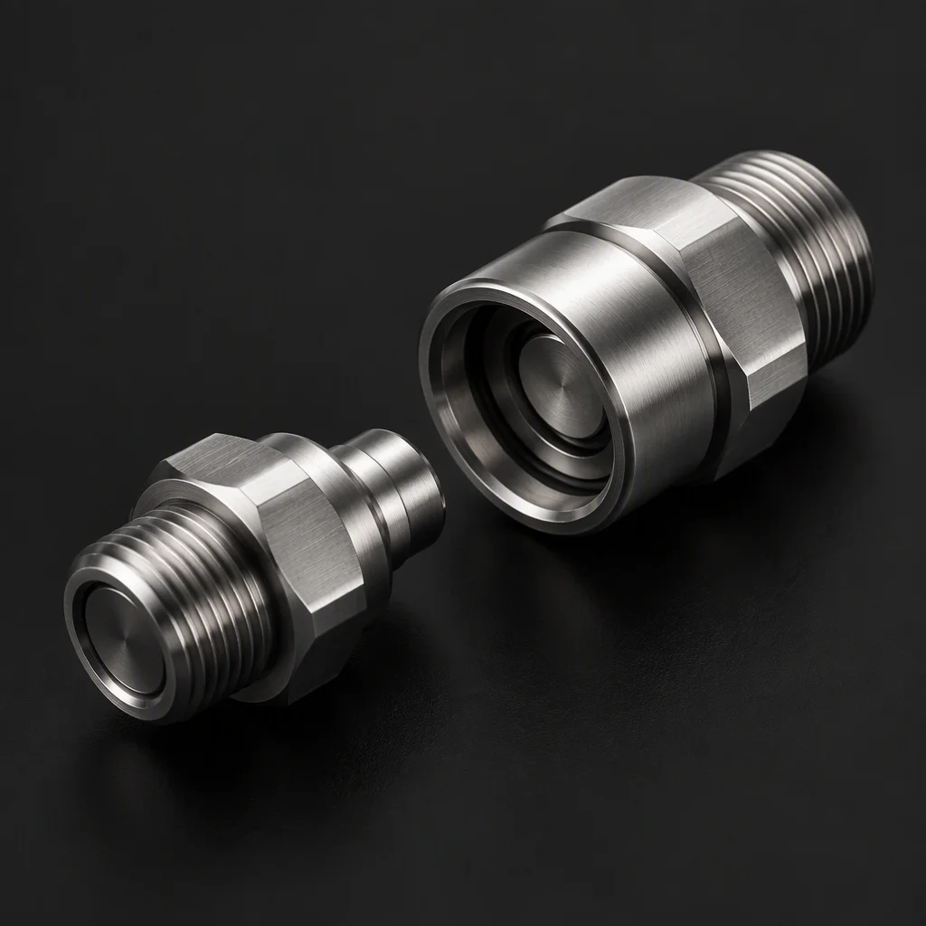
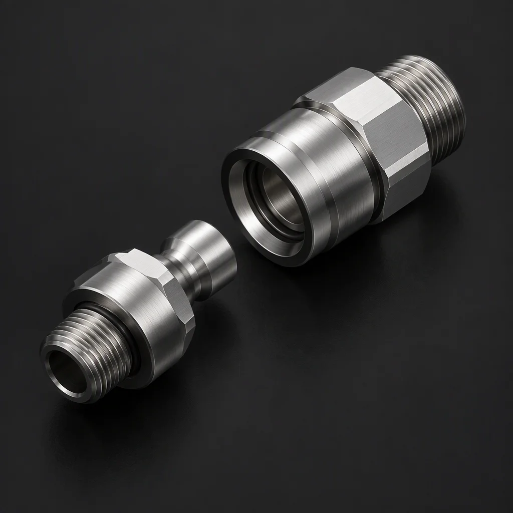
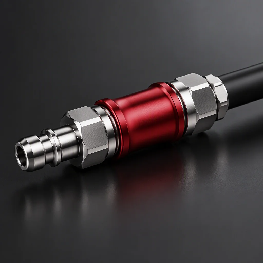
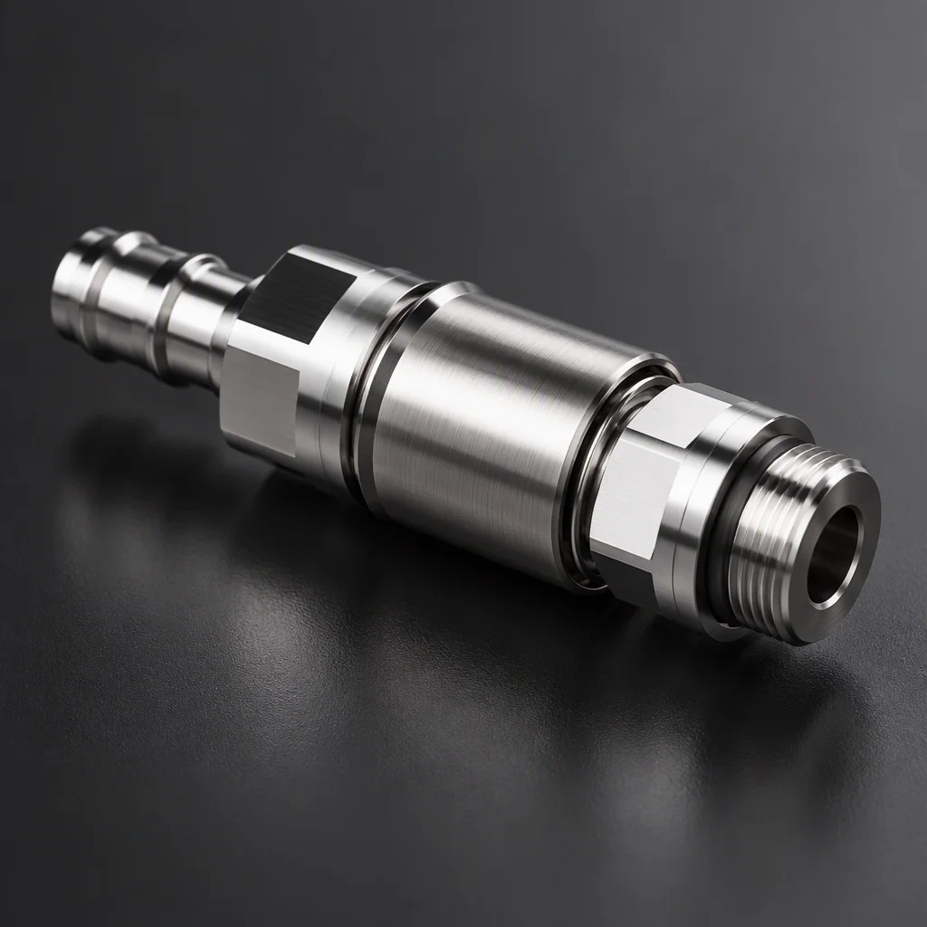
One blind-mate pair, plug and receptacle facing each other, bare stainless (generated image)

UQDB · blind-mate couplings

UQDB03 (1/8", non-spill structure only), UQDB04 (1/4"), UQDB06 (3/8"). Blind-mate is its own document family, with a sliding self-alignment interface (per OCP UQDB specification).

UQDB line
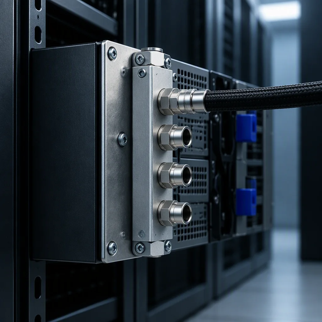
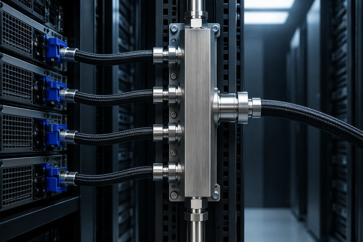
A short vertical manifold section with one row of ports (generated image)

Rack manifolds · vertical & horizontal

EIA 42U / 48U / 52U and ORv3 44OU frames; 42–52 connection points per rack. Rear-0U vertical and front horizontal forms both support top or bottom feed, one or both sides (industry-published benchmark).

Manifold line
Seven couplings in two rows: four hand-connect bores above three blind-mate bores, on a dark plate (generated image)

Seven size tiers, three lines

Orderable tiers only · UQDB05 is not a published size

The orderable matrix in one frame · UQD02/04/06/08 · UQDB03/04/06
UQD · four hand-connect bores

  • UQD02 hand-connect coupling pair, 1/8 inch bore (generated image)
    UQD02 1/8" bore
    per OCP UQD specification
  • UQD04 hand-connect coupling pair, 1/4 inch bore (generated image)
    UQD04 1/4" bore
    per OCP UQD specification
  • UQD06 hand-connect coupling pair, 3/8 inch bore (generated image)
    UQD06 3/8" bore
    per OCP UQD specification
  • UQD08 hand-connect coupling pair, 1/2 inch bore (generated image)
    UQD08 1/2" bore
    per OCP UQD specification

UQDB · three blind-mate bores

  • UQDB03 blind-mate pair, 1/8 inch class, bare stainless (generated image)
    UQDB03 1/8" · non-spill structure only
    per OCP UQDB specification
  • UQDB04 blind-mate pair, 1/4 inch class, bare stainless (generated image)
    UQDB04 1/4" bore
    per OCP UQDB specification
  • UQDB06 blind-mate pair, 3/8 inch class, bare stainless (generated image)
    UQDB06 3/8" bore
    per OCP UQDB specification

One plate per line

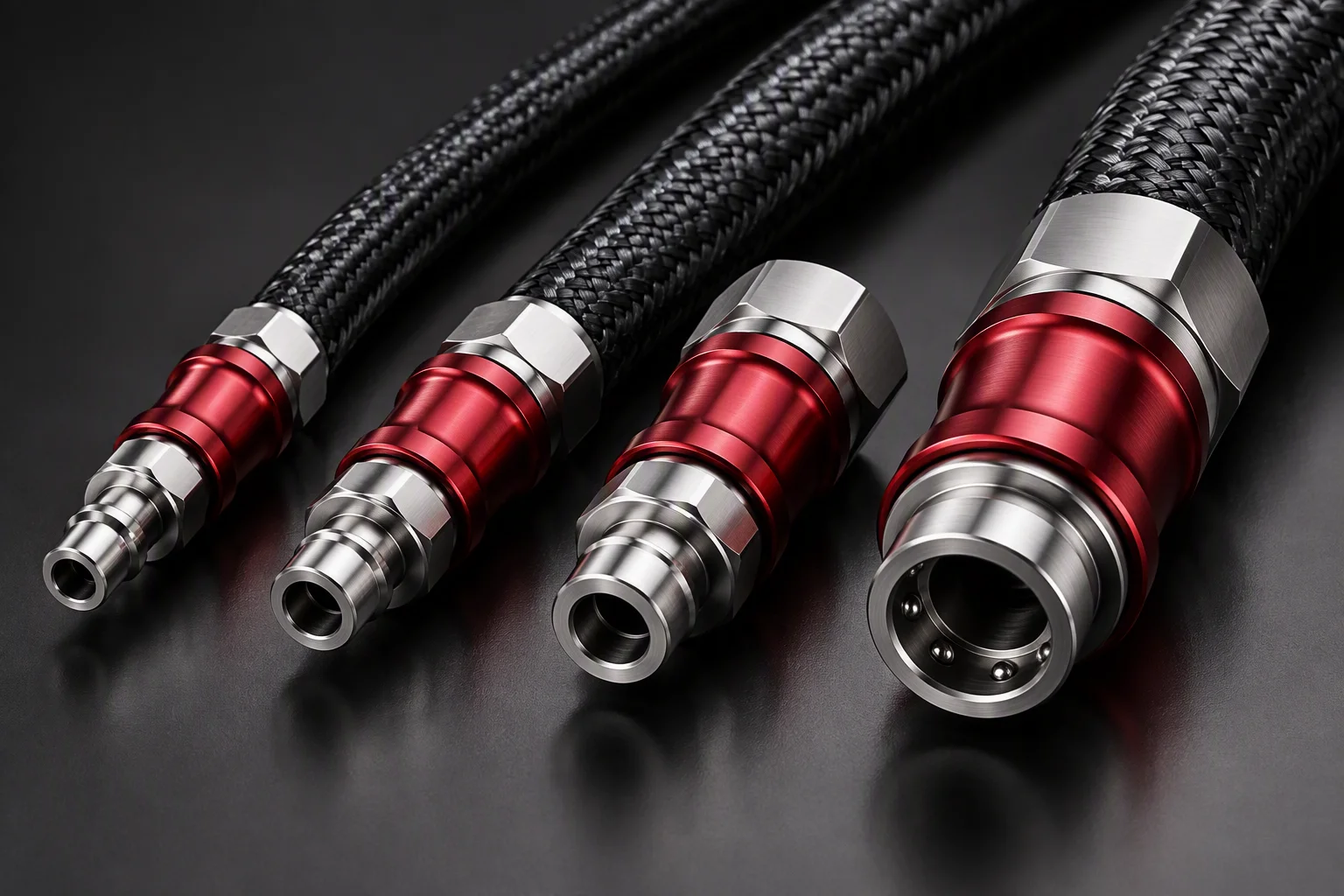
  • Four UQD couplings of increasing bore in one row, each joined to a thicker hose (generated image)
    UQD Four bores, one ascending row
  • The UQDB blind-mate family arranged on a dark ground, bare stainless (rendering)
    UQDB The blind-mate family on a dark ground
  • A full-height vertical manifold on a rear rack post, braided hose alongside (generated image)
    Manifolds Vertical 0U on a rear post
Brushed-metal grain crossing a cold dark field, low contrast (generated image)

Which segment takes which bore

Application split · industry guide

Loop schematic: a supply header and a return header with three tap points

Supply on the upper rule · return on the lower one; the marked head is the return direction (the accent event of this screen).

CPU + GPU cold plate loops
UQD04 · 1/4"

The working bore of a cold-plate tray loop (industry guide).

UQD04
High-density multi-node
UQD06 · 3/8"

Panel-mounted sockets, more nodes per frame (industry guide).

UQD06
Rack & CDU backbone
UQD08 · 1/2"

The trunk between rack and CDU (industry guide).

UQD08

Send the loop drawing for a sizing cross-check

Red and blue are specified, not decorative

Marking & traceability · per OCP UQD specification
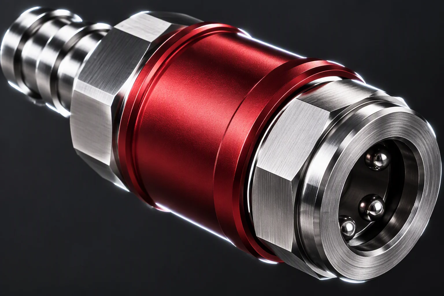
Close-up of coupling cap rings and laser-marked flats, markings unreadable (generated image)
  • Supply Colour coding at the coupling is a specification requirement: supply and return are separated at the joint (per OCP UQD specification).
  • Return Drawn in steel on this page. The second specification colour is not part of this site's palette; the real anodised colours appear in the photographs only.
  • Laser mark Part number and serial are laser-marked on the flat. The serial is what a maintenance team reads to place the part in the loop, and what ties it to the record.
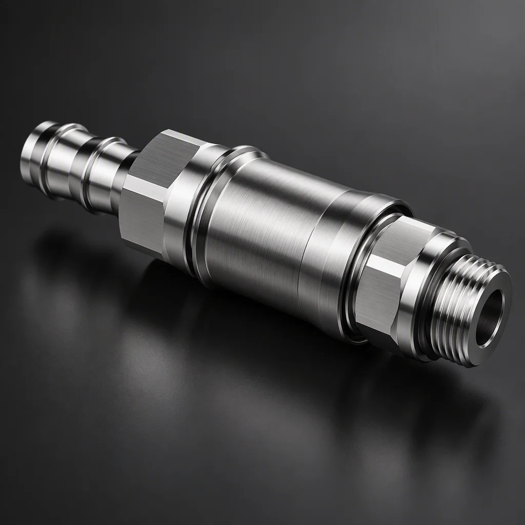
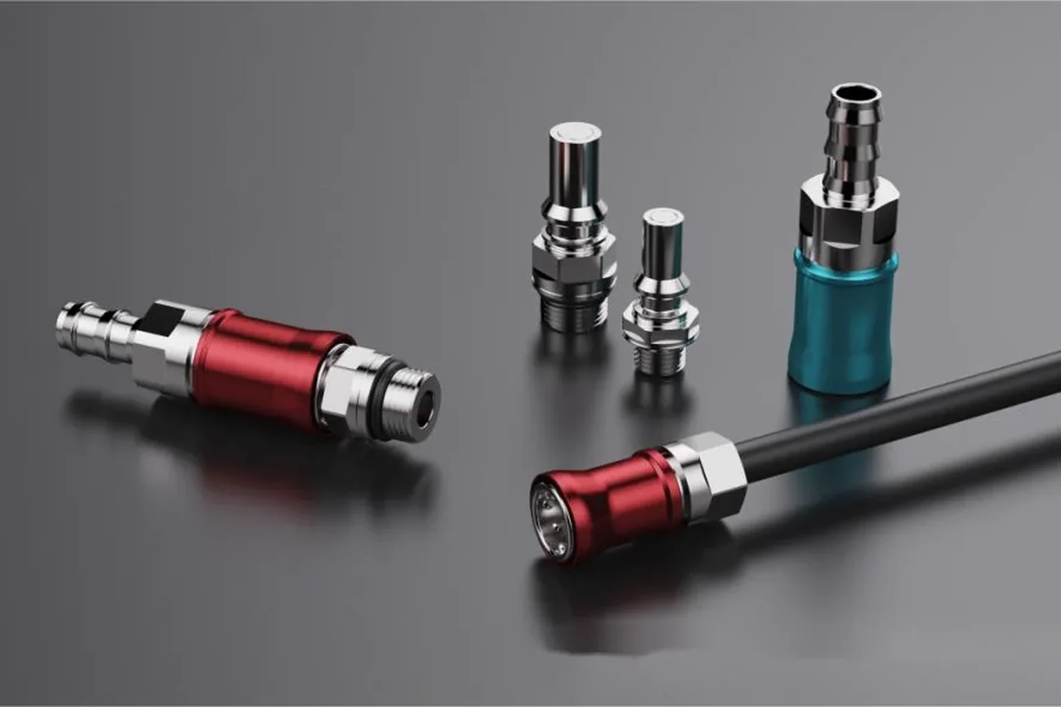
A set of UQD couplings on a dark ground, anodised rings beside bare stainless (photograph)
Anodised rings and bare stainless, same ground Photograph

Will it fit the rack you already own

Mounting & frame fit · industry-published benchmark
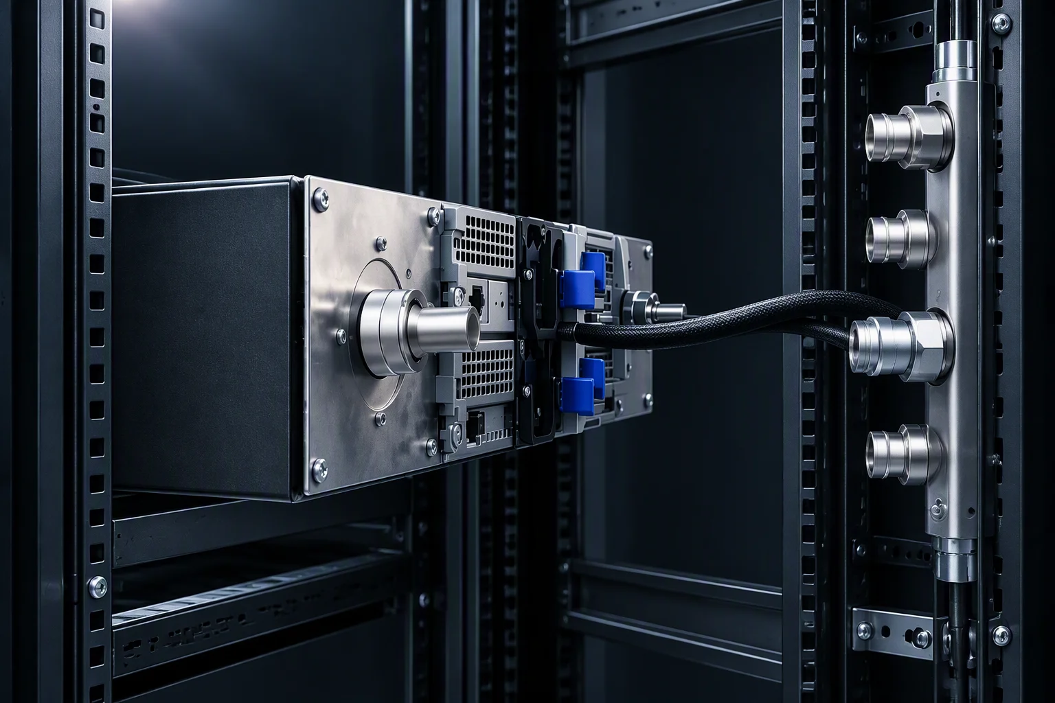
An open rack frame with a manifold on the rear post, braided hose alongside (generated image)
Rack-height ladder: one tick per rack unit across EIA 42U, 48U, 52U and ORv3 44OU

EIA 42U / 48U / 52U · ORv3 44OU — one tick per rack unit; values overlaid as mono, never inside the drawing.

  • 01

    Vertical, rear 0U. The manifold hangs on the rear posts and costs no front bay (industry-published benchmark).

  • 02

    Horizontal, front. A cross-member form when the rear is already occupied (industry-published benchmark).

  • 03

    Feed and sides. Top or bottom feed; single-sided or double-sided, 42–52 connection points per rack (industry-published benchmark).

An abstract dark industrial field with one faint horizontal haze band (generated image)
Loop sizing review

Send the loop drawing.
Get a sizing reply.

Name the segments and the rack standard.

Request spec sheet

One business day · English quote + one-page spec sheet covering UQD02–08 and UQDB03–06