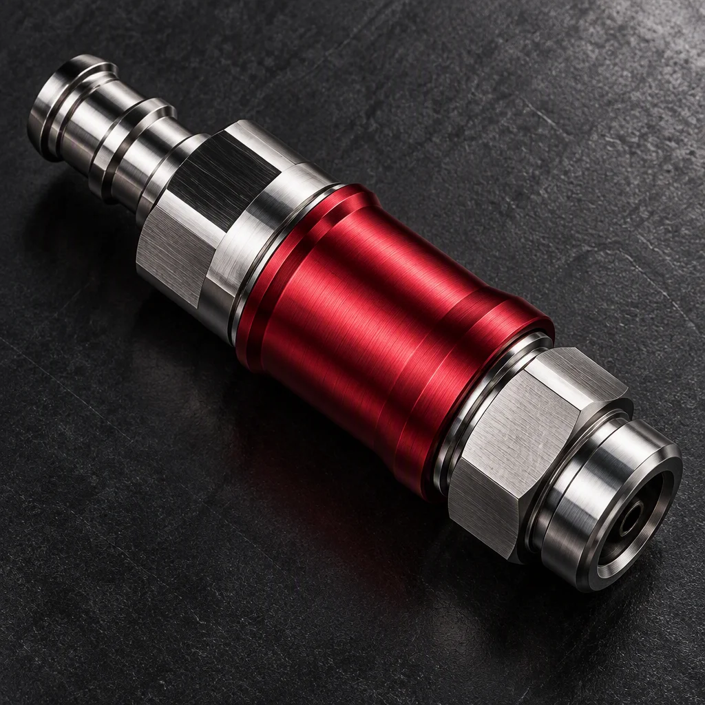
OCP UQD specification · Rev 1.0 · 2020-09-04
UQD Quick Disconnects —
OCP Universal Quick Disconnect, Rev 1.0
One open interface, four bores, and the numbers the specification fixes for each of them. Revision 1.0 is dated 2020-09-04 and originated at Intel before it was contributed to OCP as an open standard (per OCP UQD specification).
Request spec sheetA fixed interface, several suppliers
The mating interface is fixed by a bore ladder that equivalent industry parts match at 3.2 / 6.4 / 9.5 / 12.7 mm (industry practice). Seals and body materials are set by each supplier, so a cross-brand pair is verified at the sample stage and the test summary is issued for that brand pair.
The bore ladder, end to end
Nominal bore · per OCP UQD specification
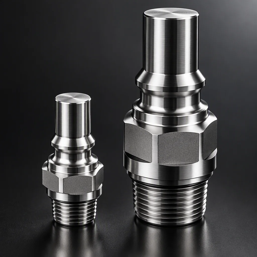
Four openings in ascending order; the values below are laid over as mono, never drawn inside the figure.
-
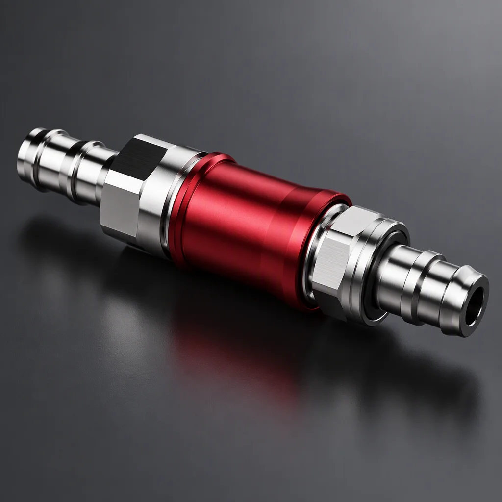
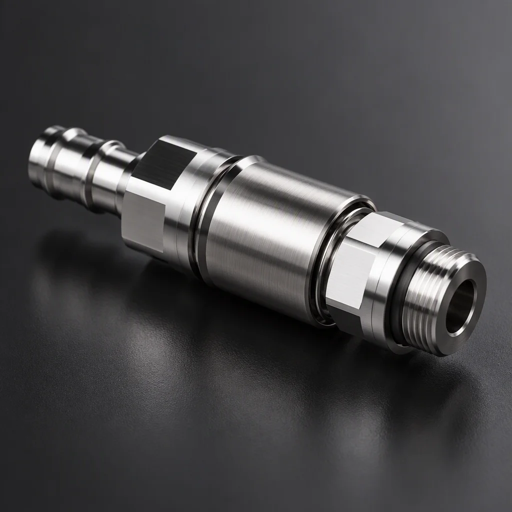 UQD02
1/8" nominal
UQD02
1/8" nominal
per OCP UQD specification 3.2 mm equivalent
industry practice -
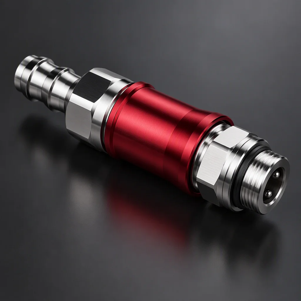
 UQD04
1/4" nominal
UQD04
1/4" nominal
per OCP UQD specification 6.4 mm equivalent
industry practice -
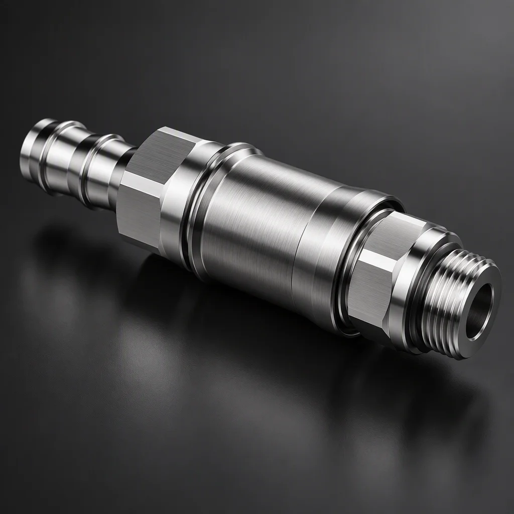
 UQD06
3/8" nominal
UQD06
3/8" nominal
per OCP UQD specification 9.5 mm equivalent
industry practice -
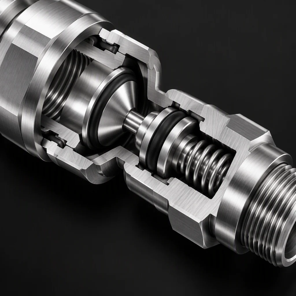
 UQD08
1/2" nominal
UQD08
1/2" nominal
per OCP UQD specification 12.7 mm equivalent
industry practice

Flow has a floor, not just a ceiling
Minimum Cv and recommended flow · water-referenced
Four ticks left to right: UQD02 · UQD04 · UQD06 · UQD08. The marked head is the 2.50 Cv end of the ladder.
-
UQD02 0.25 min Cv
0.55 GPM recommended per OCP UQD specification -
UQD04 0.80 min Cv
1.7 GPM recommended per OCP UQD specification -
UQD06 1.60 min Cv
3.0 GPM recommended per OCP UQD specification -
UQD08 2.50 min Cv
4.7 GPM recommended per OCP UQD specification
Cv figures and flow steps are water-referenced values from the specification; a coolant with a different viscosity is sized against the loop, not against this table.
Dry-break, in millilitres
Per connect / disconnect at 0 psi · per OCP UQD specification
- UQD02
- UQD04
- UQD06
- UQD08
- Loss per connect / disconnect
- 0.020 ml
- 0.025 ml
- 0.035 ml
- 0.070 ml
- Maximum water content
- 1.7 ml
- 3.2 ml
- 3.8 ml
- 5.7 ml
Both rows are specification limits: the values are the permitted maximum, not a measured average for a batch.
The family, as it arrives and as it runs
Twelve plates · four to a row · same 3:2 frame throughout
The bores themselves
-
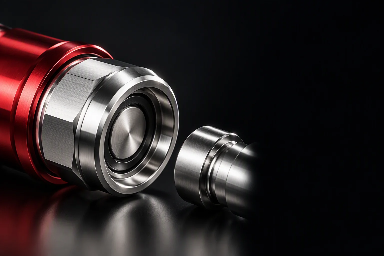
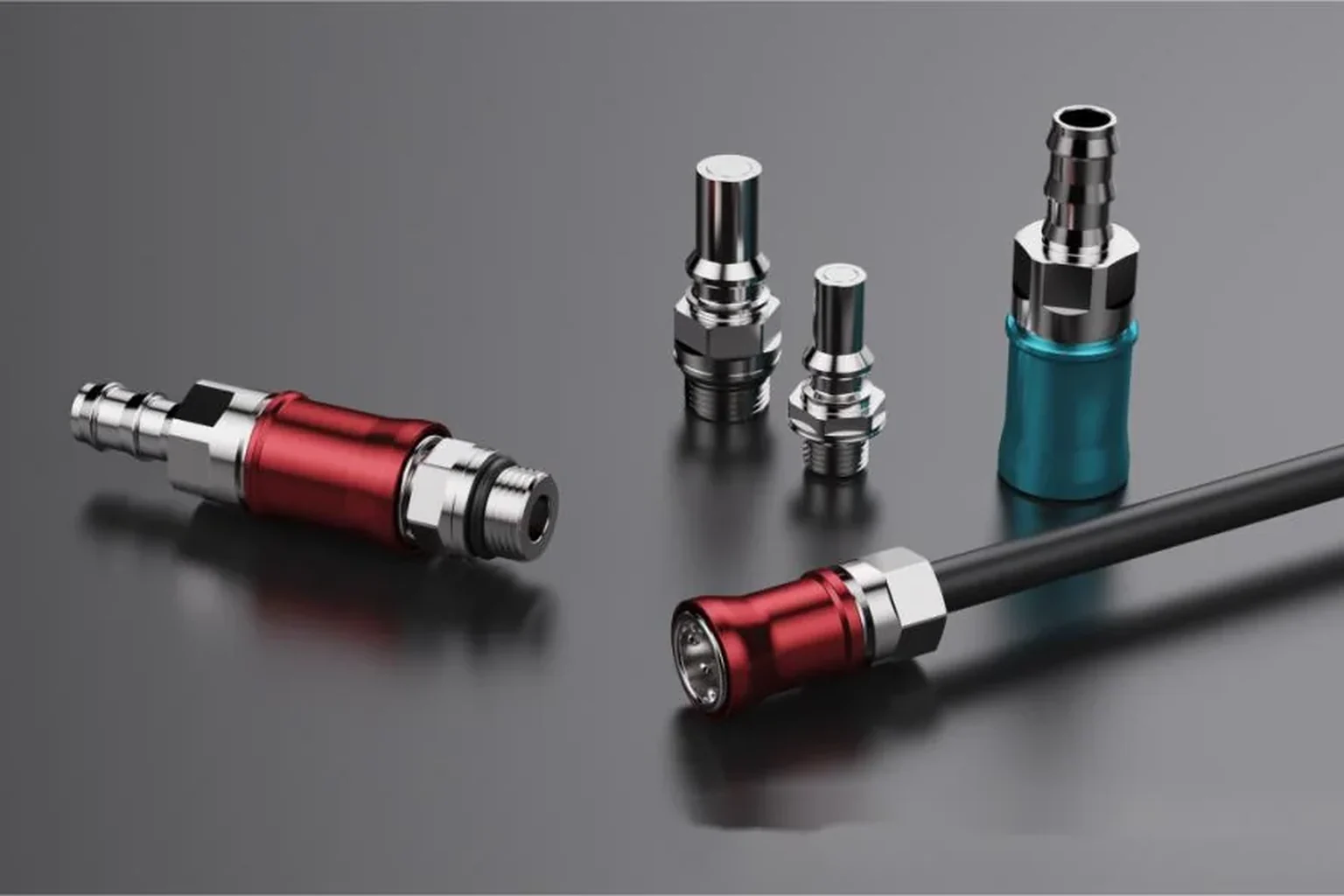 The setAnodised collars and bare stainless on one ground
 -
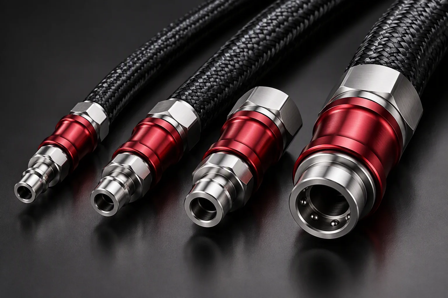 The ladderFour bores ascending in one row
 -
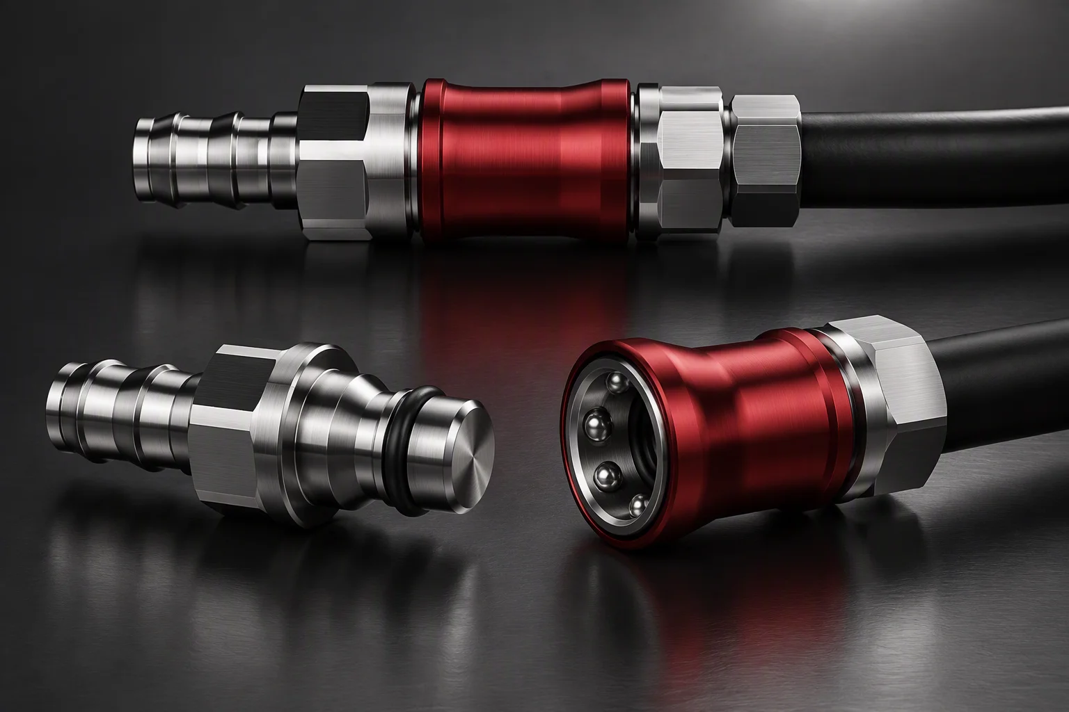 The two statesMated, and apart with both faces visible
 -
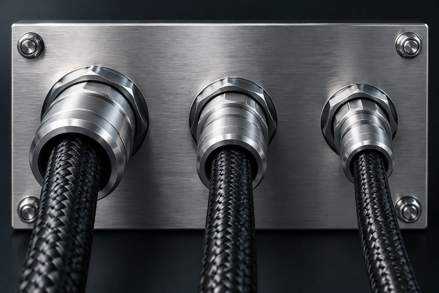 The backplateThree bores through one panel, locknuts behind
At the panel and in the tray
-
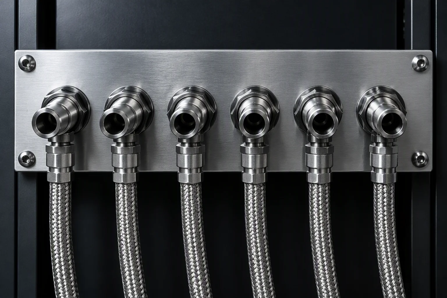 Panel bank · UQD06Six sockets in one row
 -
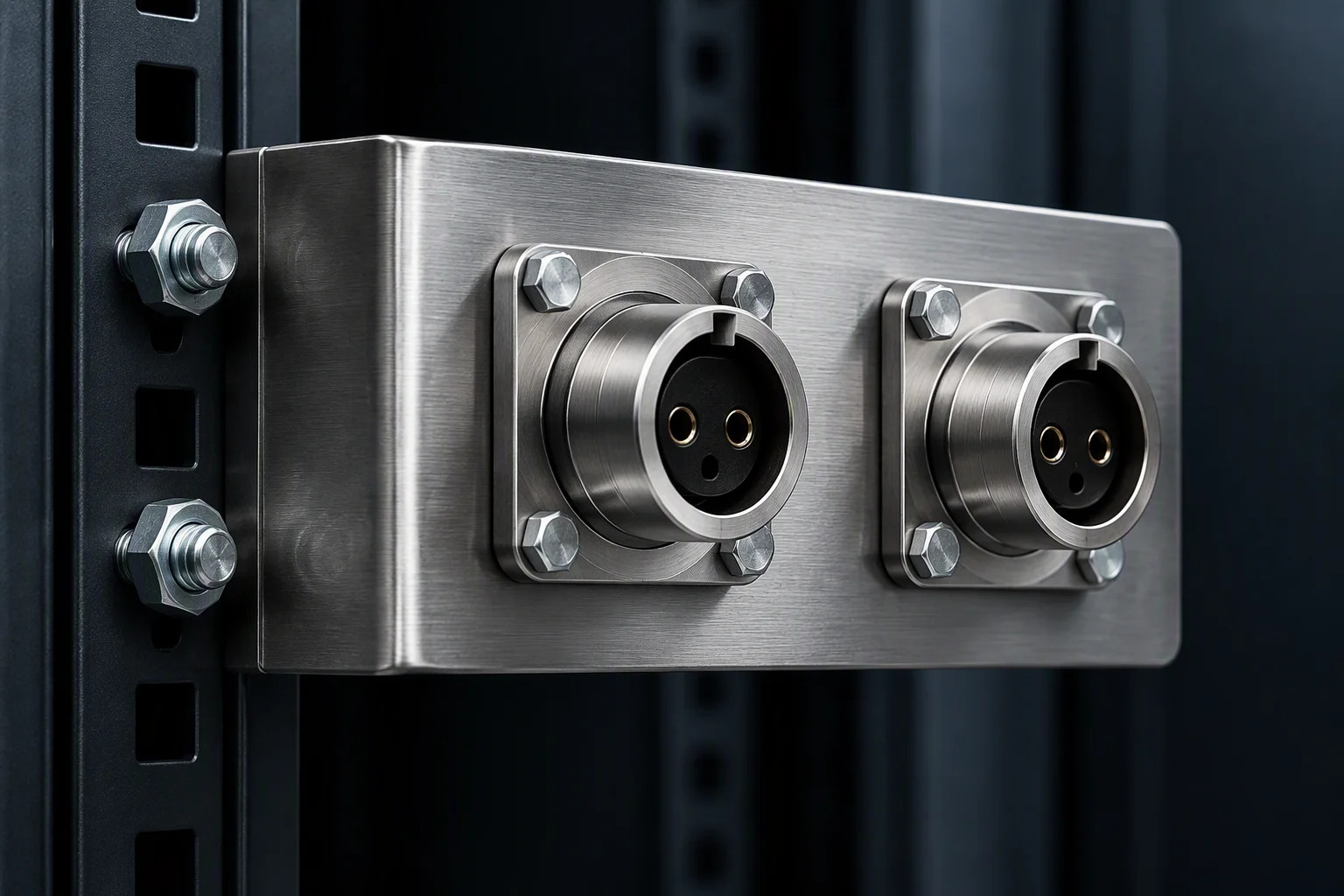 Bracket · UQD06A bent bracket on the rail
 -
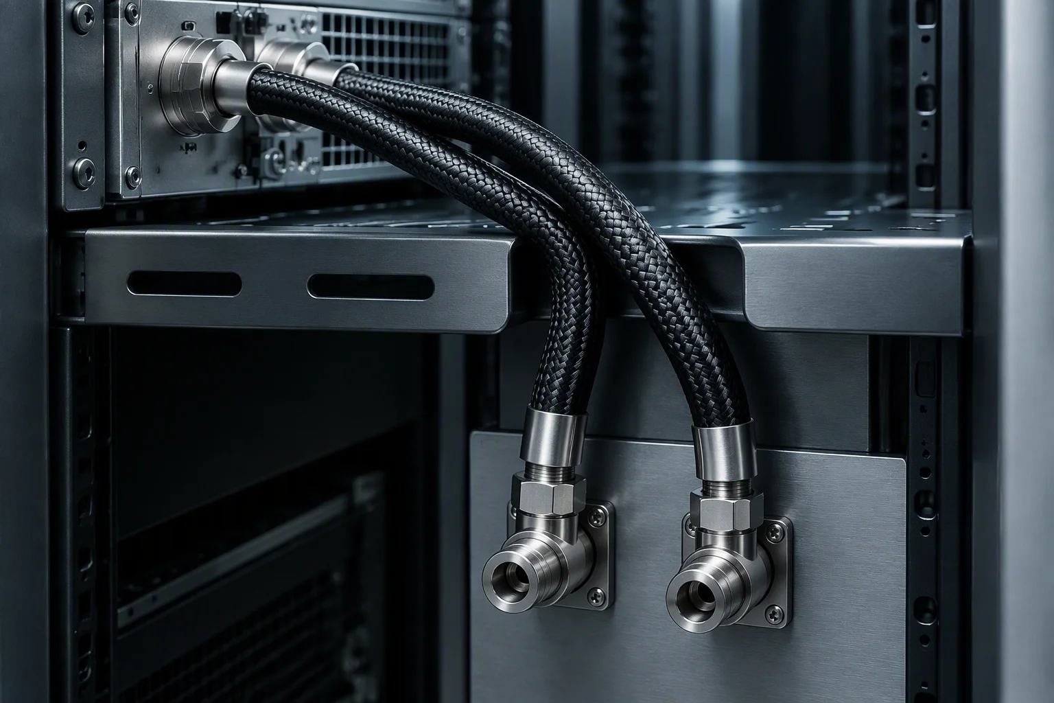 Tray route · UQD06A hose pair over the tray edge
 -
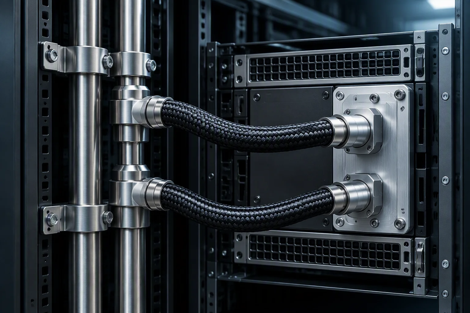 Loop routePipe pair feeding a cold plate
Runs, interfaces and spares
-
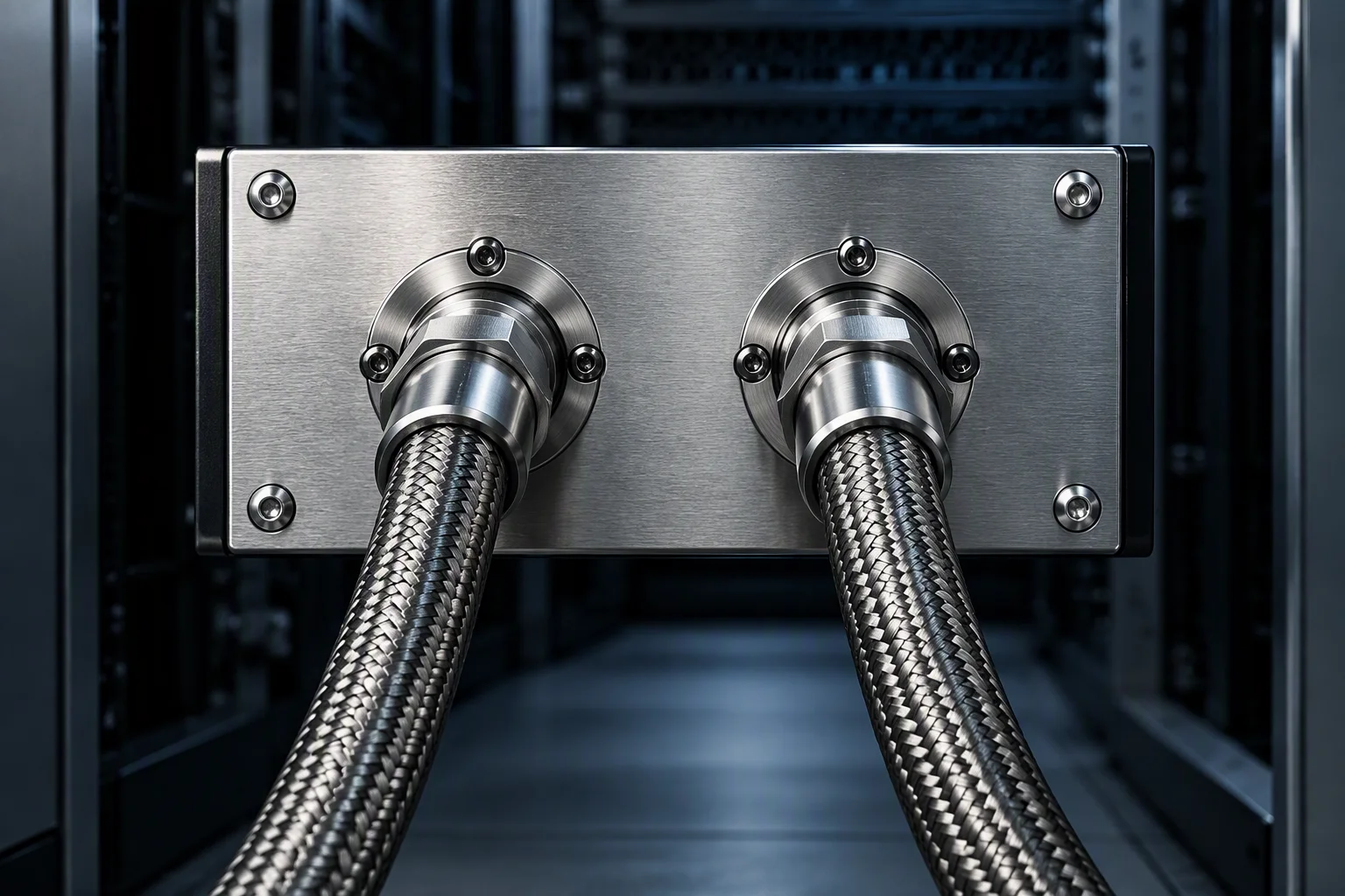 CDU interface · UQD08A port pair on the CDU face
 -
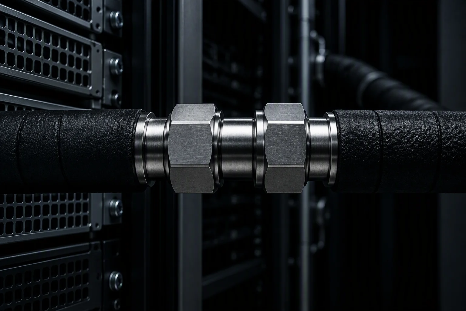 Trunk run · UQD08Inline on the insulated trunk
 -
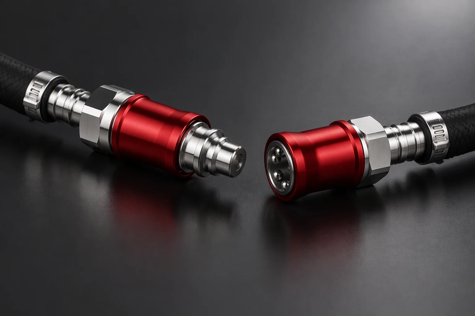 Spare · UQD04Plug and socket, as shipped apart
 -
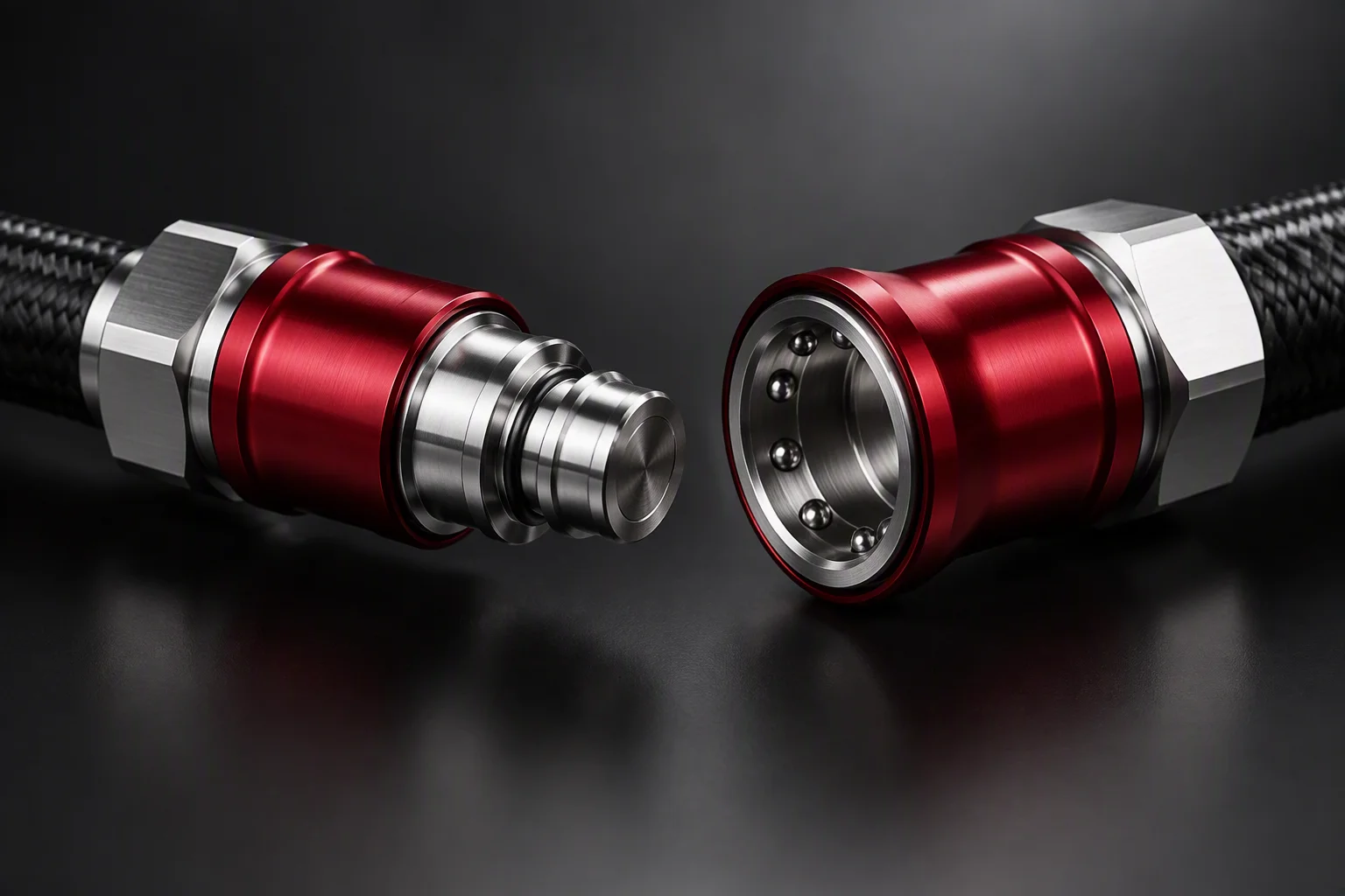 Spare · UQD08The wide end of the ladder, apart
Pressure envelope
Two specification values and one industry ceiling
Ratings are per-interface, not per-loop System proof and burst are set against the loop drawing
Mixing brands is a test, not an assumption
Mating interface · industry practice
-
01
The interface is fixed. The pair is defined by a bore ladder that equivalent industry parts match across 3.2–12.7 mm (industry practice).
-
02
Seals and materials are not. Each supplier sets its own seal compound and body material, so two parts can share a bore and still differ at the face.
-
03
So we test the pair you will run. Cross-brand pairing is verified on samples, and the test summary is issued for that brand pair — not for the bore size in general.

Name the bore.
Take the data sheet.
Tell us the bore or the loop segment. One business day brings an English quote and a one-page spec sheet covering UQD02–08 and UQDB03–06 (designed to OCP UQD/UQDB specification).