Rack manifolds — supply and return distribution
A supply header, a return header and one row of quick disconnect ports, mounted on the rack, sized to the rack standard you already build to.
Request a port mapPorts, header outside diameters and pressure: industry designs · uniformity target: industry practice

One pair of headers between the rack loop and the CDU.
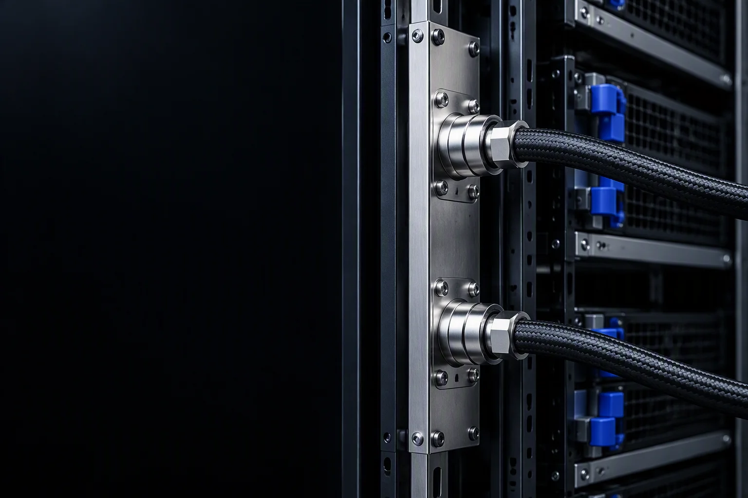
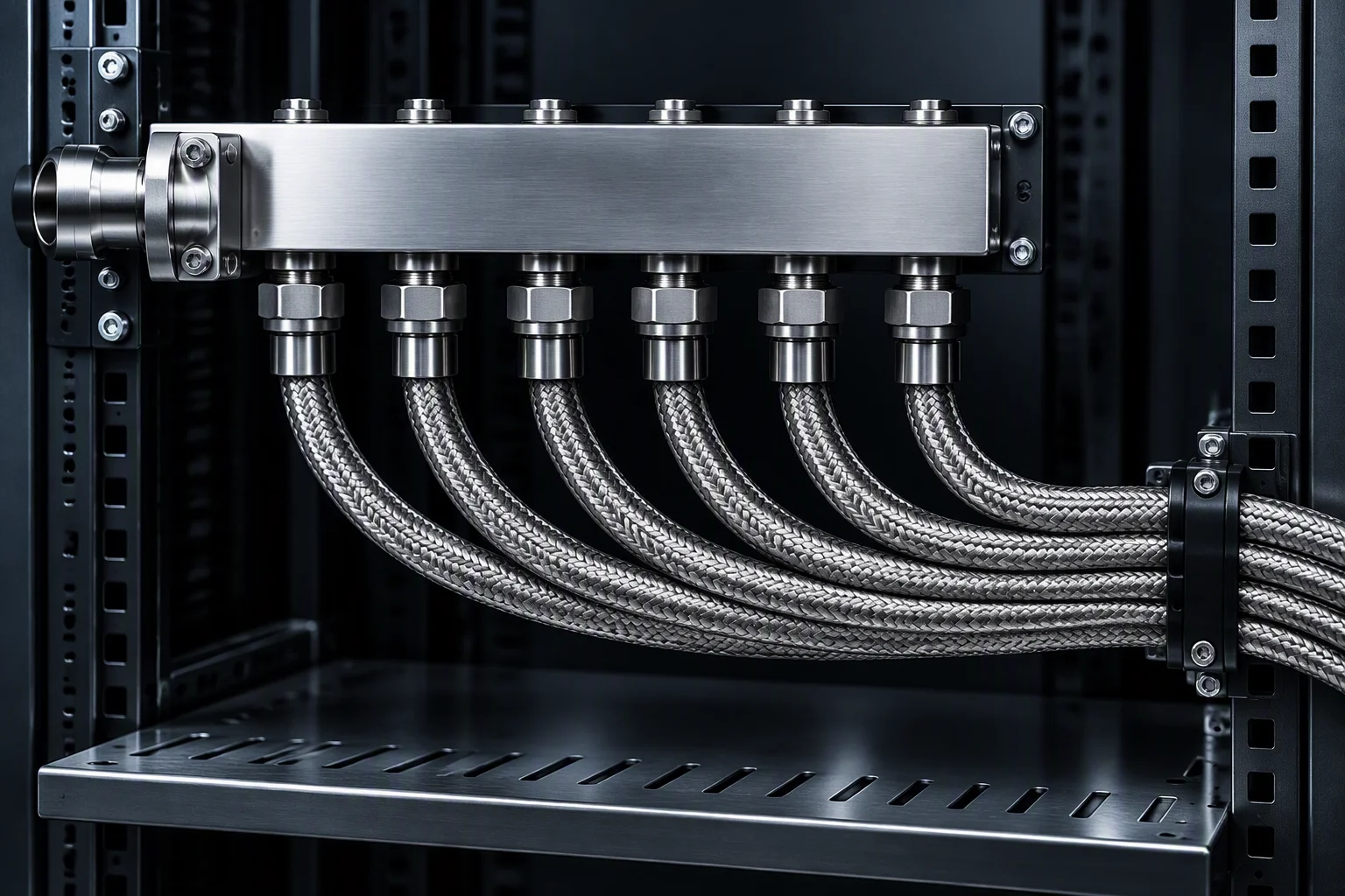
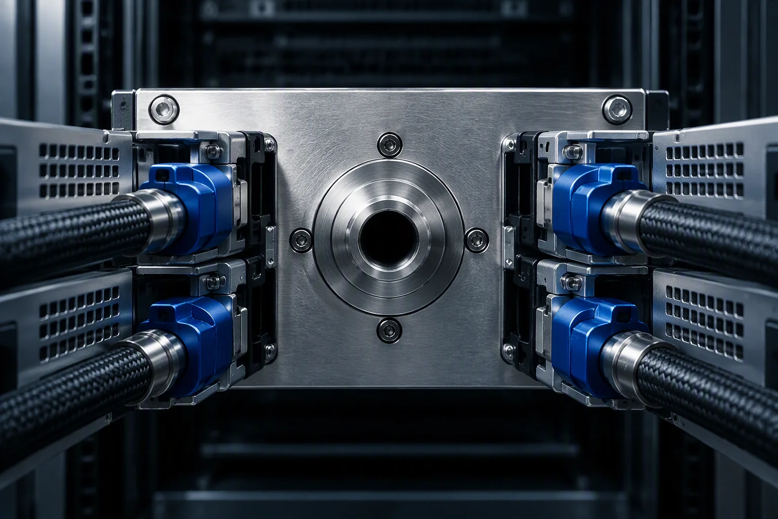
The manifold is where a row of server loops meets the building side of the system. Rear-of-rack mounting leaves the U space and the front service face untouched; industry practice puts a 0U manifold in exactly that position.
Rear 0U mounting position · industry practice
Three flow layouts
U / Z / I · industry practice · the red line marks the return path only
U · supply and return on one side
Z · crossing feed
I · straight through
Red line = return path
Which of the three fits is decided by where the CDU feed arrives and which face of the rack stays open for service, not by preference. Port contacts are drawn as open circles; every one of them is a quick disconnect port.

Configuration
Six values · industry designs
Pick the mounting family
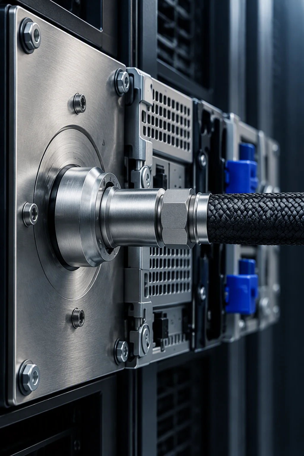
Three bay-wide options · one rack standard each

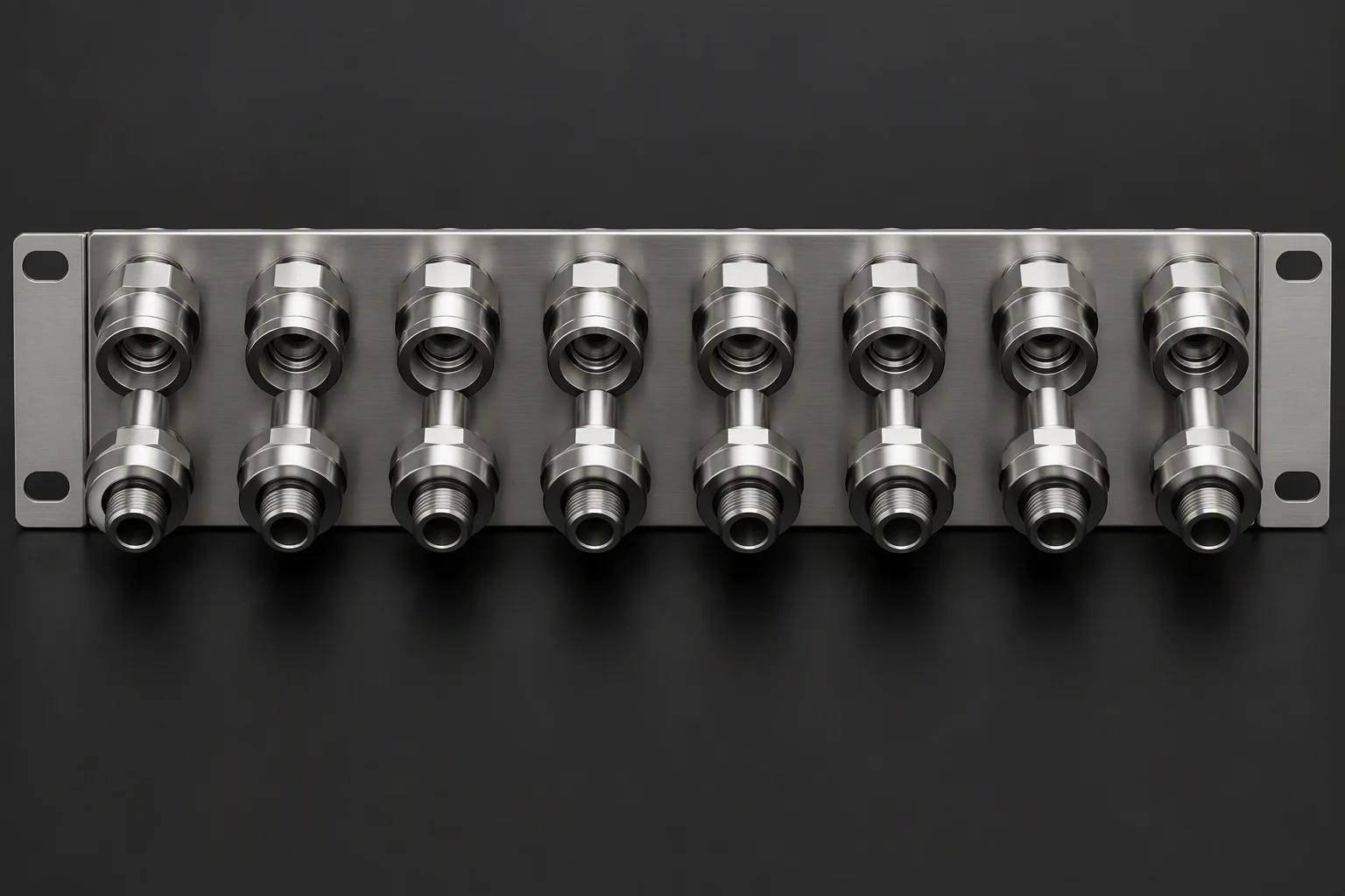
What the ports take
Interface types · shipping condition

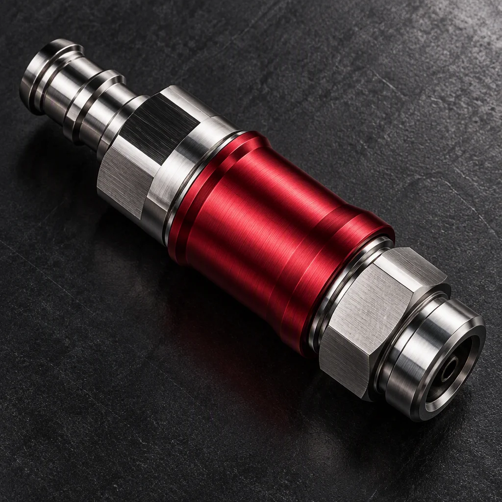
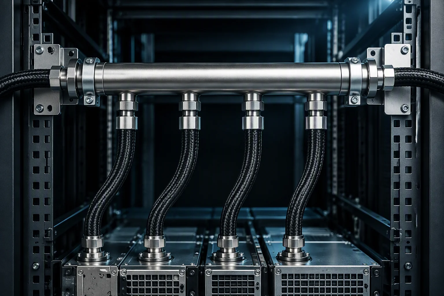
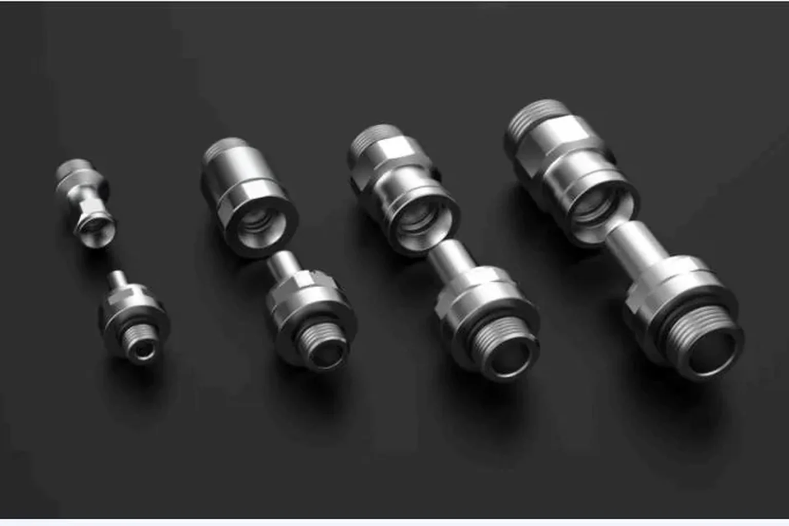
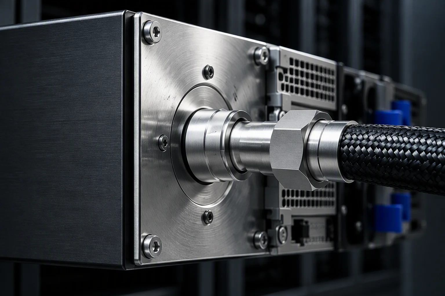
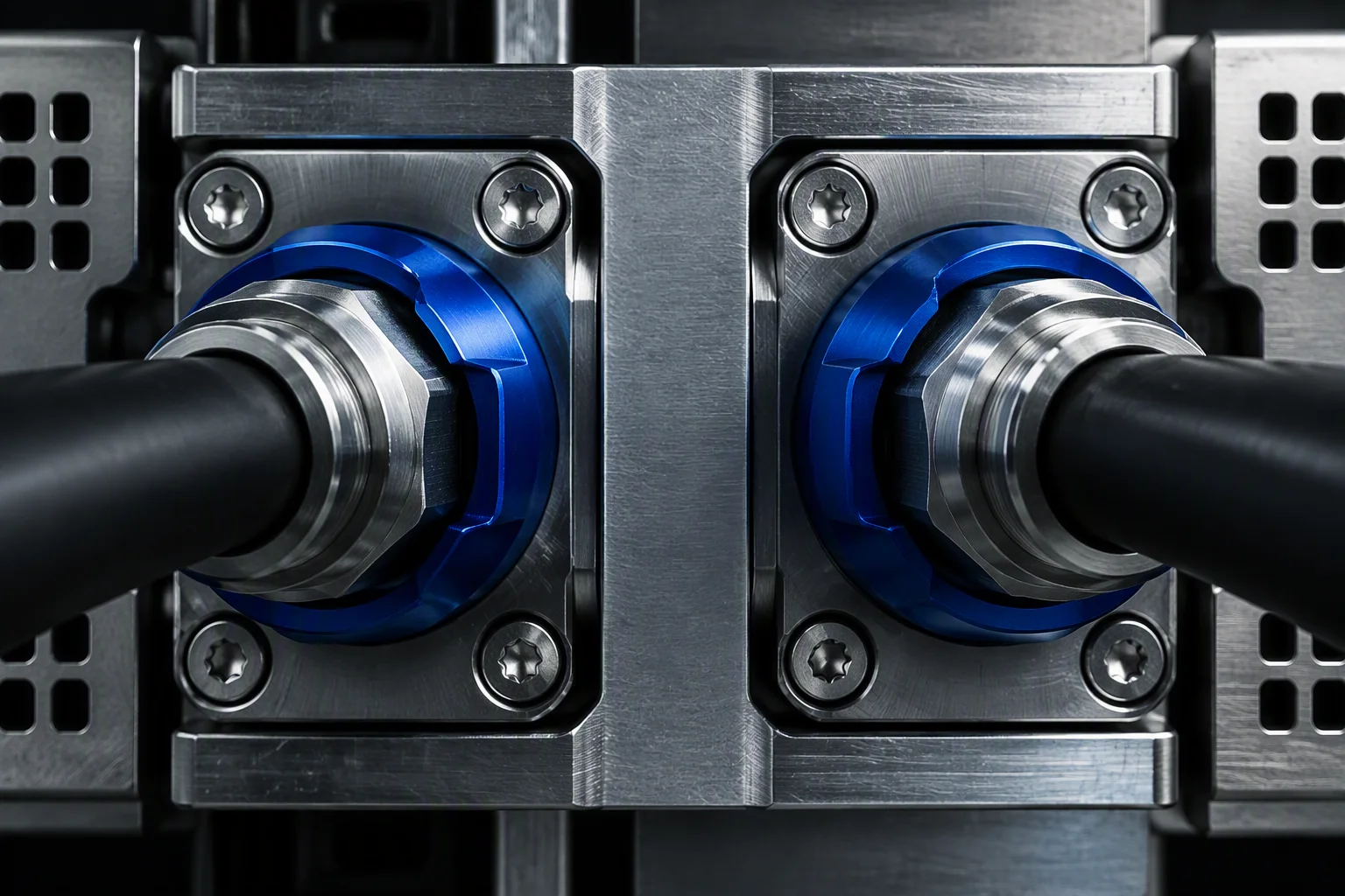
A manifold port can be a plain threaded boss, a hand-mate quick disconnect or a blind-mate socket, and all three can sit on the same header. What has to be fixed at the drawing stage is which port goes where, because the tray side is built against that drawing.
Discussed: FD83 ports · hand-mate ports · blind-mate sockets · shipping caps and supply/return marking
Installed, by flow layout
Mount states and port rows · three families




Hydraulic performance
Three values · industry practice
Sizing starts at about 1.5 L/min per kW of rack heat load; the uniformity target is a design target, and the acceptance band on test is the wider one. Source: industry practice.
Request the hydraulic and port-map sheetVerification and rack fit
Per-unit leak test · rack adaptation
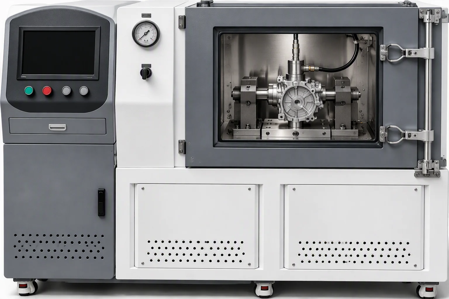
Every manifold is leak tested per unit, including each quick disconnect port, under static and dynamic conditions. That test routine is industry practice; it is not a mark or a certificate held by DryLink.
Per-unit leak test incl. every port · static and dynamic · industry practice
Rack adaptation runs against EIA 42U / 48U / 52U and the ORv3 44OU standard, with 42–52 connection points in the standard configuration.
EIA 42U / 48U / 52U · ORv3 44OU · 42–52 connection points · industry-published benchmark
Send the rack elevation and the port map is drawn on it, port by port, against the standard you build the rack to.

Which rack standard?
Send the rack elevation, the node count and the rack standard (EIA or ORv3). Sizing starts at about 1.5 L/min per kW of rack heat load.
Request a port mapOne business day · English quote + one-page spec sheet · designed to the OCP UQD specification