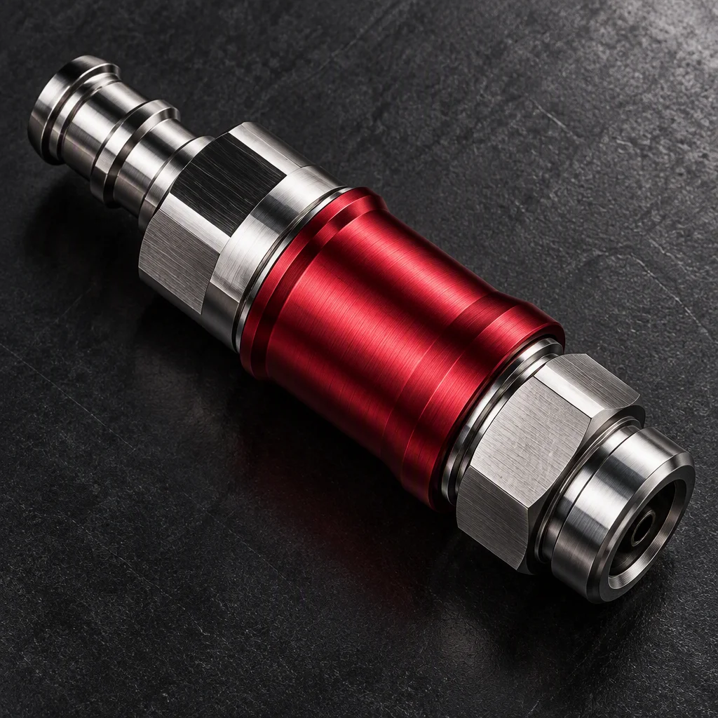
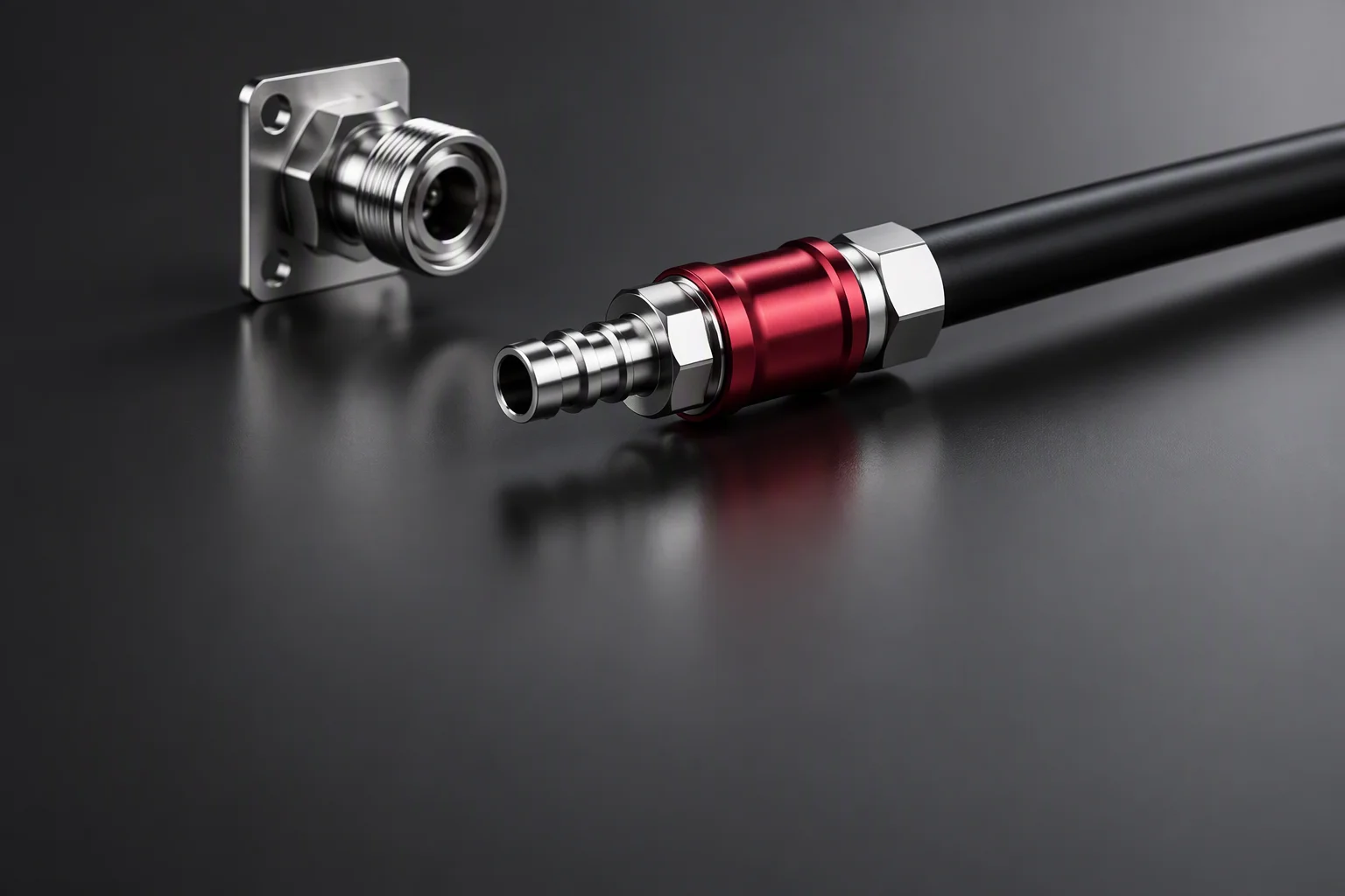
UQD06 · 3/8 inch · high-density multi-node
UQD06 (3/8") Quick Disconnects
for High-Density Nodes
The bore that gets panel-mounted, serviced live, and counted in cycles. Three numbers decide the service case: cycles, working pressure, and the loop you leave behind the panel.
Request spec sheetFix the socket before you think about servicing it
Panel mount · per OCP UQD specification
Backplate, reinforcement plate, socket, and the loop the hose is allowed to take. Dimensions sit in the mono layer, never in the drawing.
-
01
Mount the socket. The specification prescribes panel-mount sockets with a reinforcement plate (per OCP UQD specification). A socket hanging on its hose is not the same part in service.
-
02
Let the plate take the load. The reinforcement plate keeps hose load and vibration off the coupling body, so the seal face sees pressure rather than a bending moment (per OCP UQD specification).
-
03
Leave a service loop. Reserve roughly three hose lengths behind the panel — that is what the hand needs when the node comes out (per OCP UQD specification).
Service the node without draining the loop
Live service · industry practice
-
01
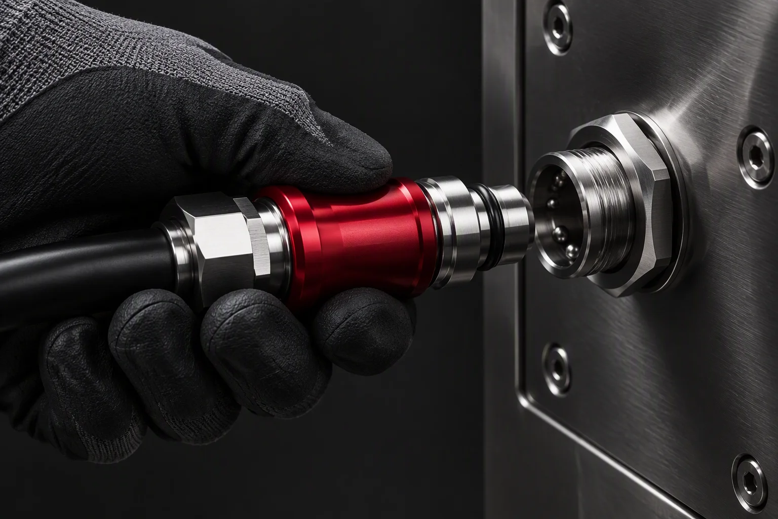
Under pressure is normal. Industry parts in this class support connect and disconnect under pressure, which is what makes an online service window possible (industry practice).
-
02
Two colours, one rule. Colour marking separates supply from return at the joint (industry practice) — the specification requires it, and a maintenance team reads it before it reads a label.

Cycles, and who stands behind the count
Cycle interval · industry guide
Left end: 10,000 cycles. Right end: 50,000 cycles — the marked head. Values are overlaid here as mono, not drawn inside the figure.
-
01
The interval. Well-made couplings in this class reach 10,000–50,000 connect / disconnect cycles, far beyond the specification's endurance floor (industry guide).
-
02
Per batch, not per brochure. Cycle data is supplied against the production batch that ships, so it can be written into an acceptance clause as a document rather than a claim.
-
03
What sets the count. Coolant, torque at the panel and how the hose is routed all move the number. Send the tray drawing and the count is quoted for that build.
Pressure headroom
Industry parts in this class · industry guide
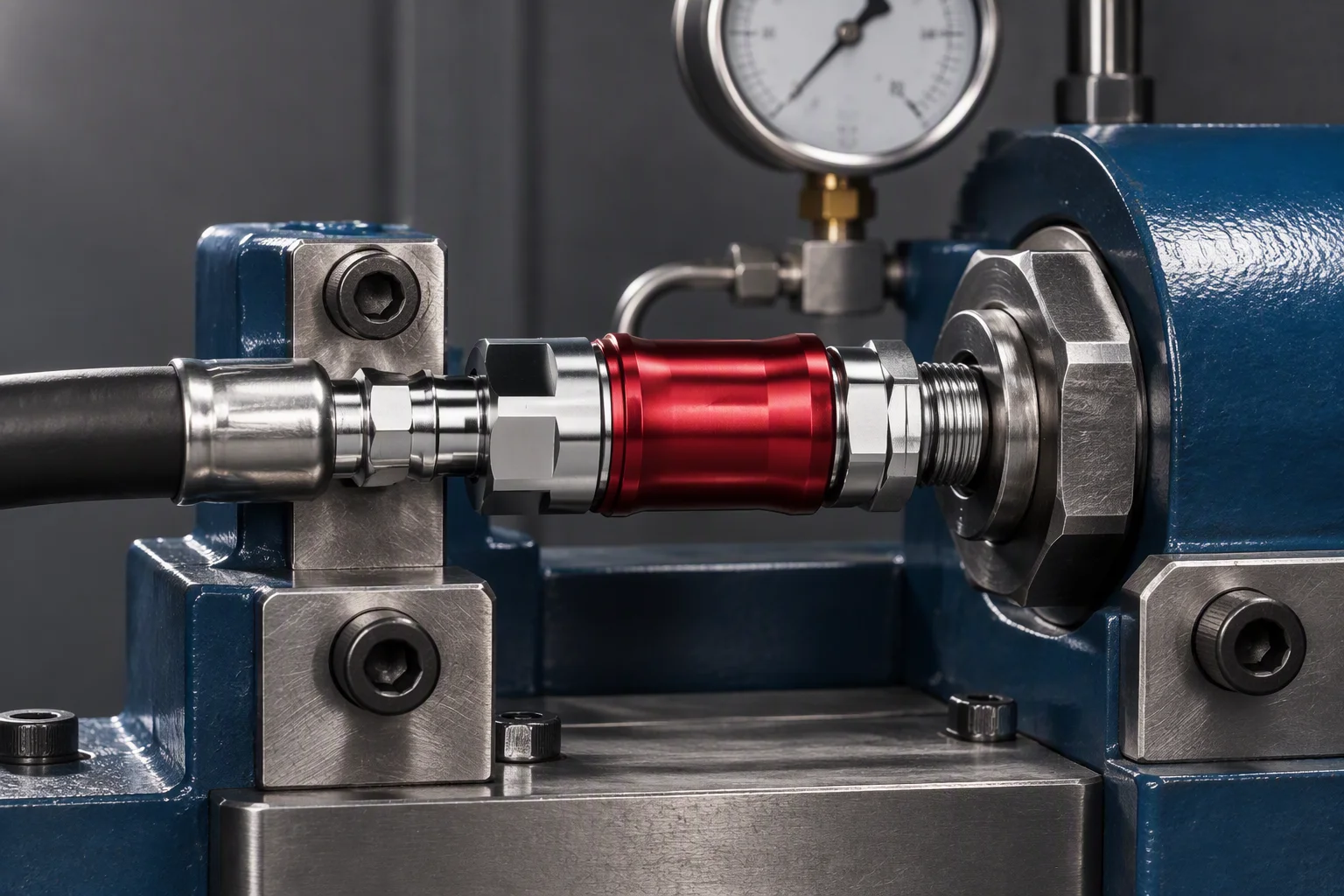
A transient spike is a loop question, not a coupling question: relief settings are reviewed against the site's pressure curve before the bearing part is chosen.
Panel, tray, rack, batch
Twelve plates · four to a row
At the panel
-
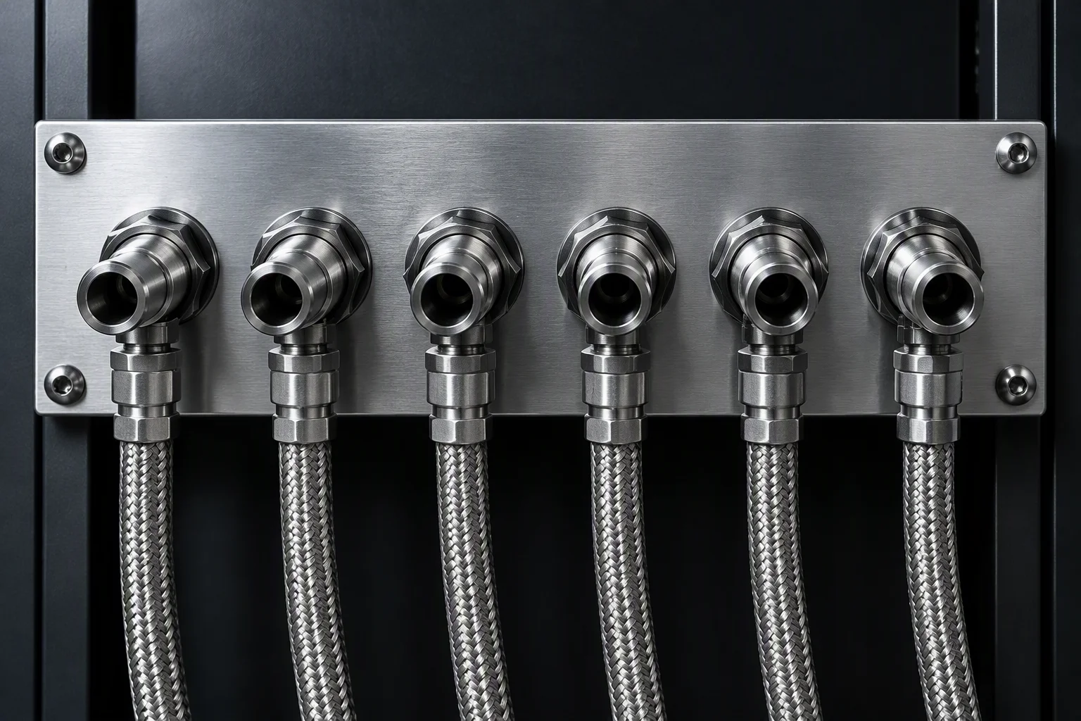 Six-up bankSix sockets, one row, one panel
 -
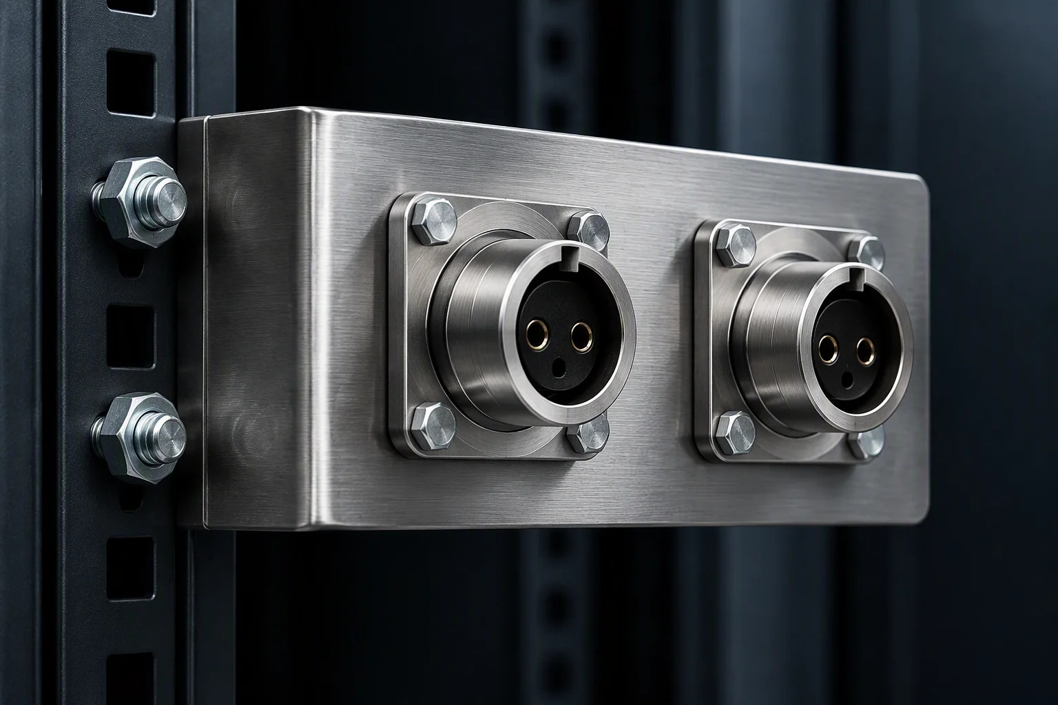 BracketTwo sockets on a bent bracket
 -
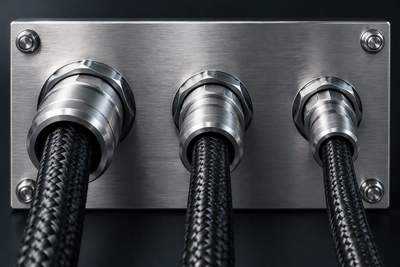 BackplateMixed bores through one plate
 -
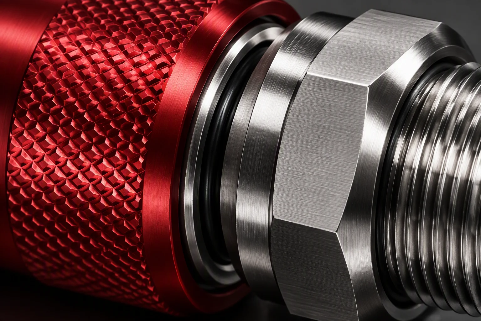 Lock sleeveThe sleeve a gloved hand turns
In the tray and in the rack
-
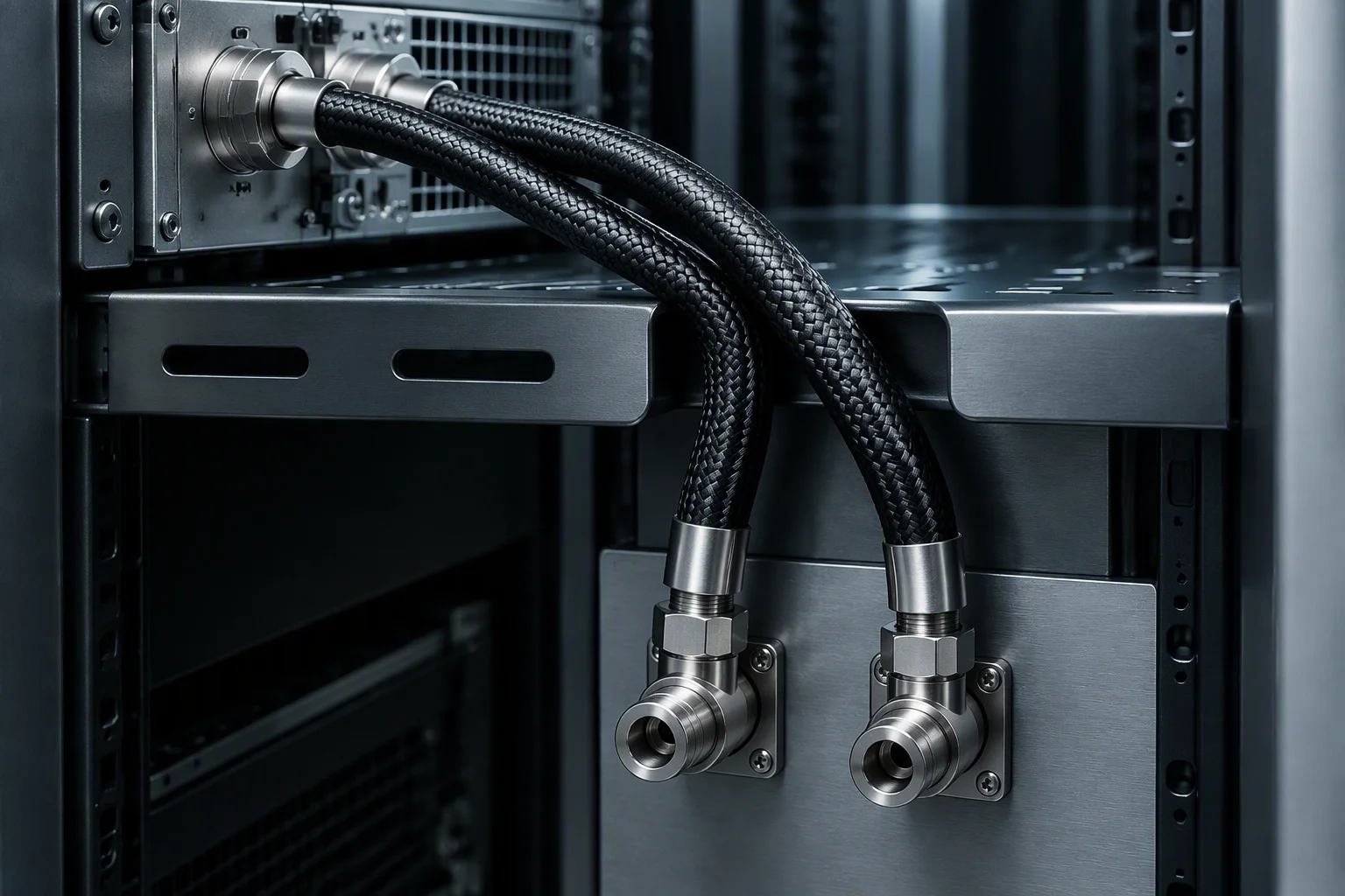 Tray routeHose over the tray edge, no kink
 -
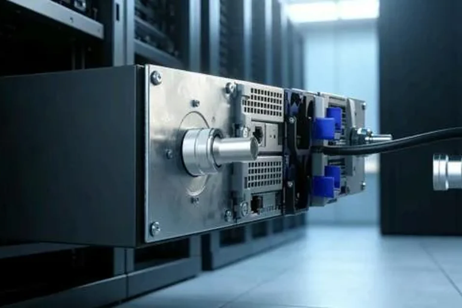 Rack sideA rack face with couplings and hose
 -
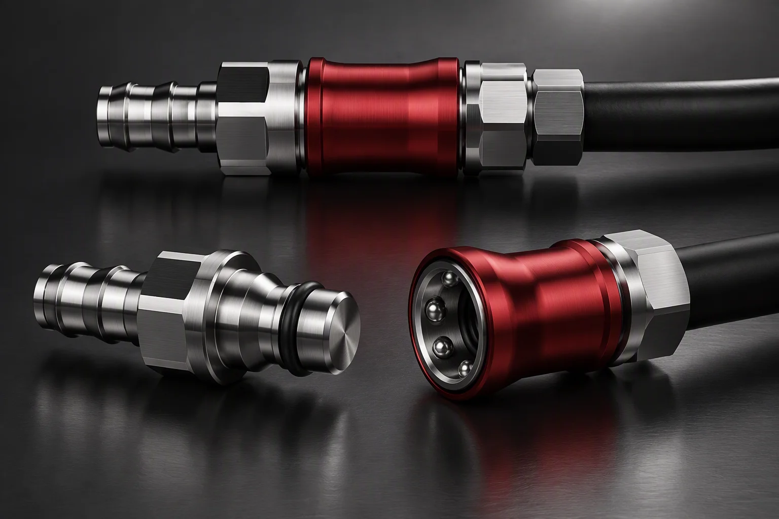 Two statesMated and apart, one pair
 -
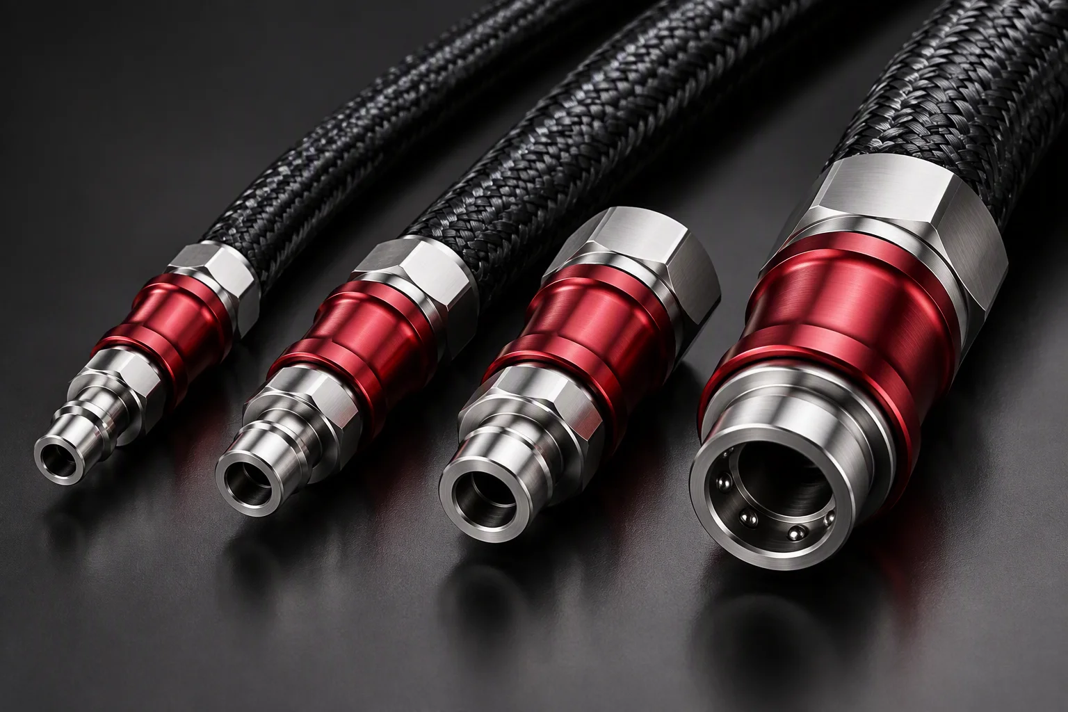 Position in the familyFour bores ascending — this one is third
The bore and the stack
-
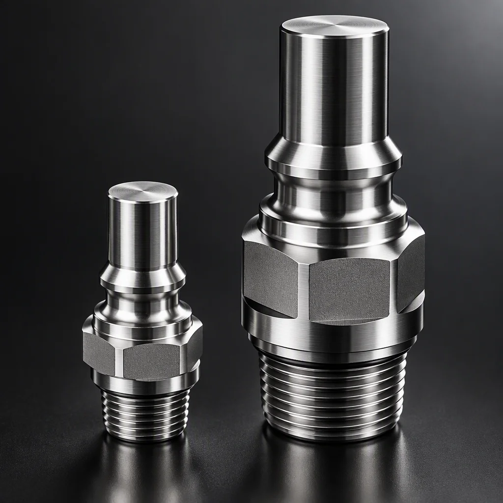 Family extremesThis bore against the two ends of the ladder
 -
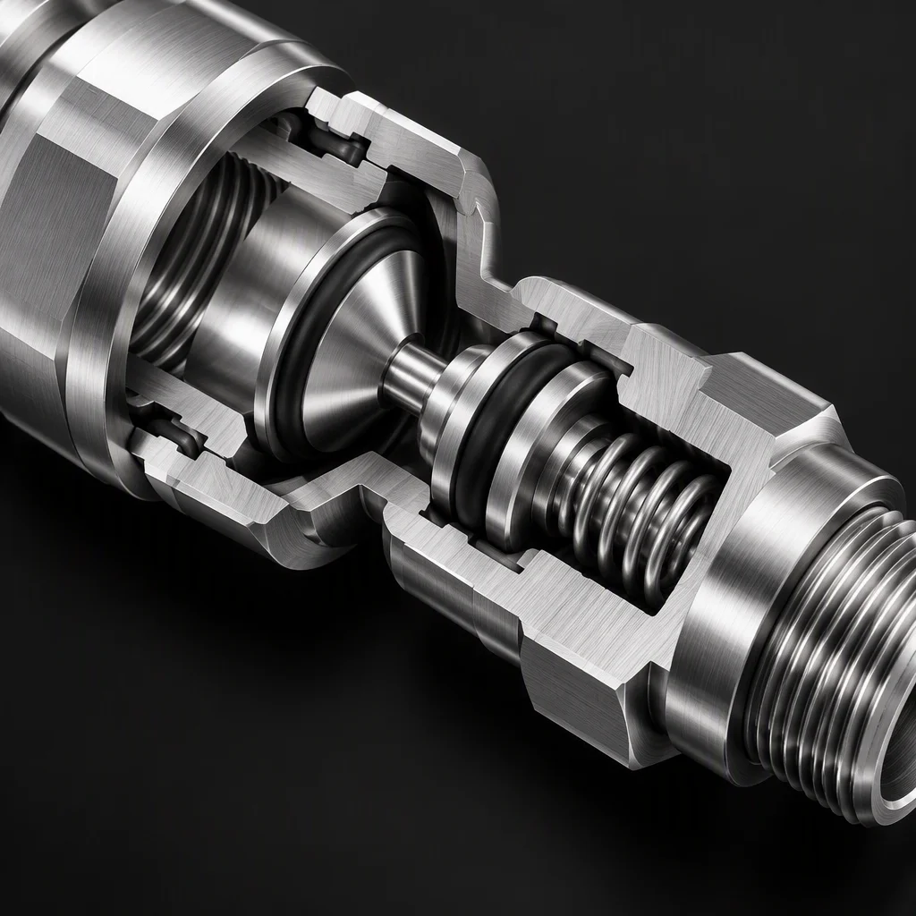 Dry-break stackThe valve that holds pressure during service
Where it is made, and the batch it ships in
-
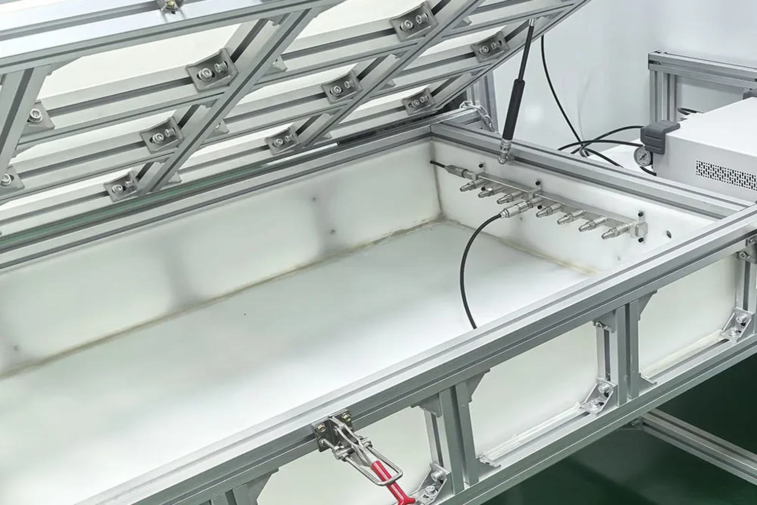 Test benchTrough, fitting rail and gauge
 -
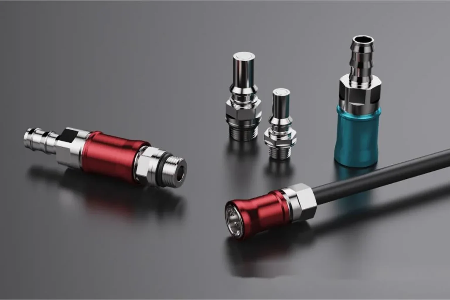 The batchCycle data is issued against this, not a type

Send the tray drawing.
Get the stack and the count.
Panel layering, bracket position and the service loop all come off your model. One business day brings an English quote and a one-page spec sheet for UQD02–08 and UQDB03–06.