
Welding & fabrication
A welded part is a pressure part
Laser welding for the straight runs, vacuum brazing for the joints a single pass cannot reach. Neither is accepted on appearance: every welded assembly is proof-tested on its own.
Every welded assembly proof-tested at ≈1.5× WP · industry practice
Send the WP
Two joining processes, two jobs
Laser weld · vacuum braze
Laser welding
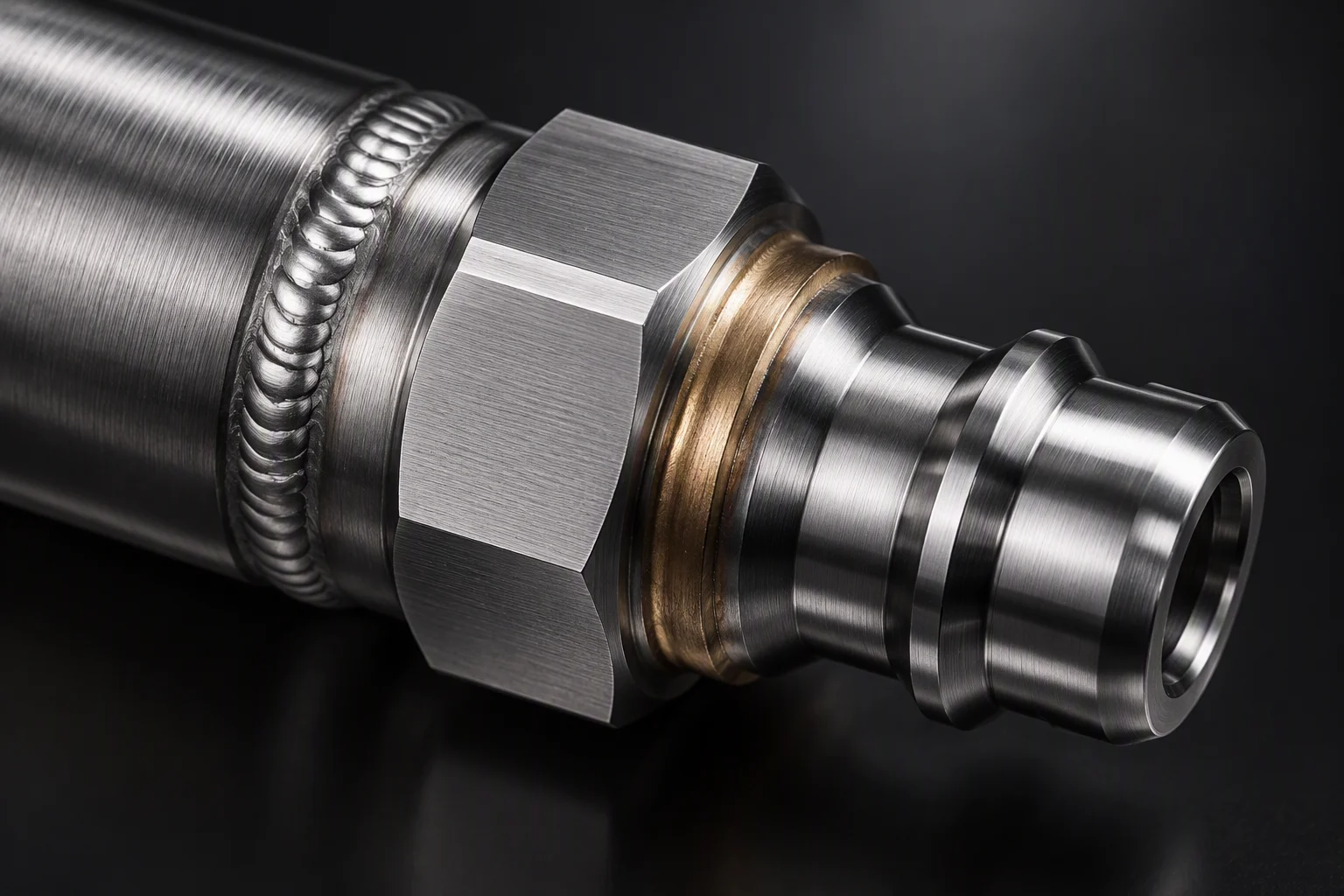
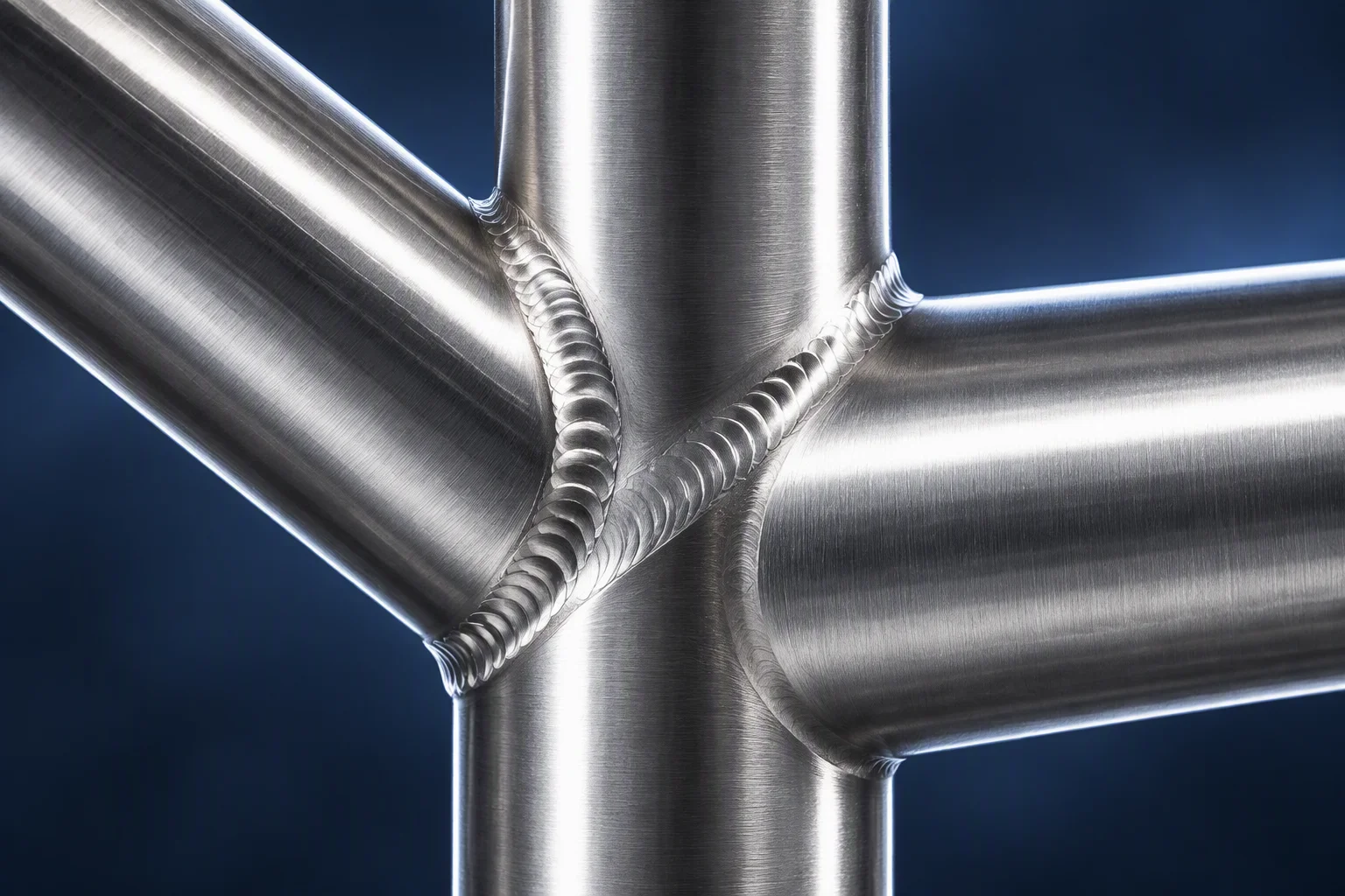
Narrow heat-affected zone and low distortion on thin-wall tube, which is what keeps a long manifold straight after joining. industry practice
Vacuum brazing
Used on the complex joints where a weld torch cannot reach both sides of the seam. industry practice
Parameters
Recorded per station, so a joint can be traced to the settings that made it. process capability
Weld samples
Archived by batch rather than discarded after the run. process capability
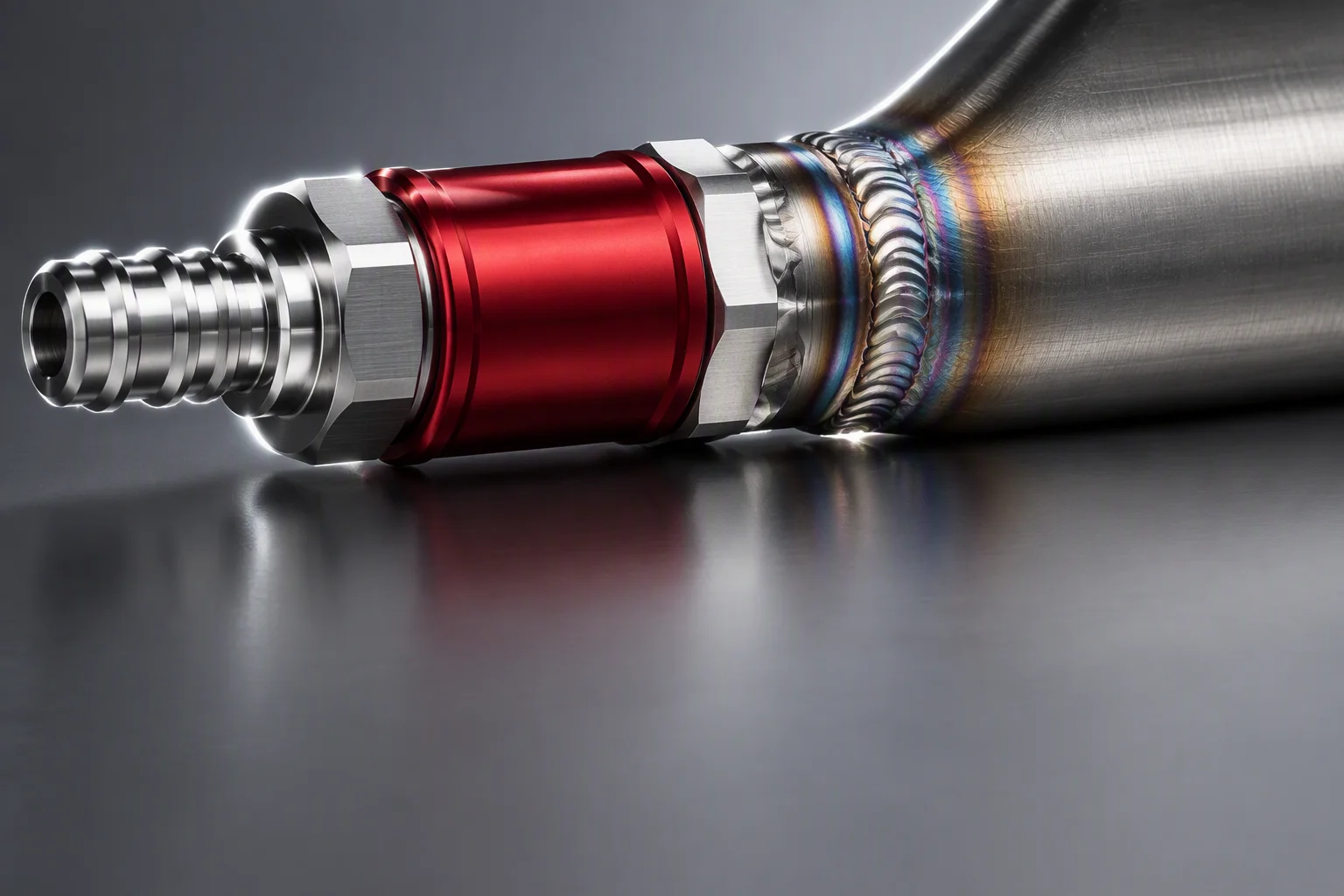
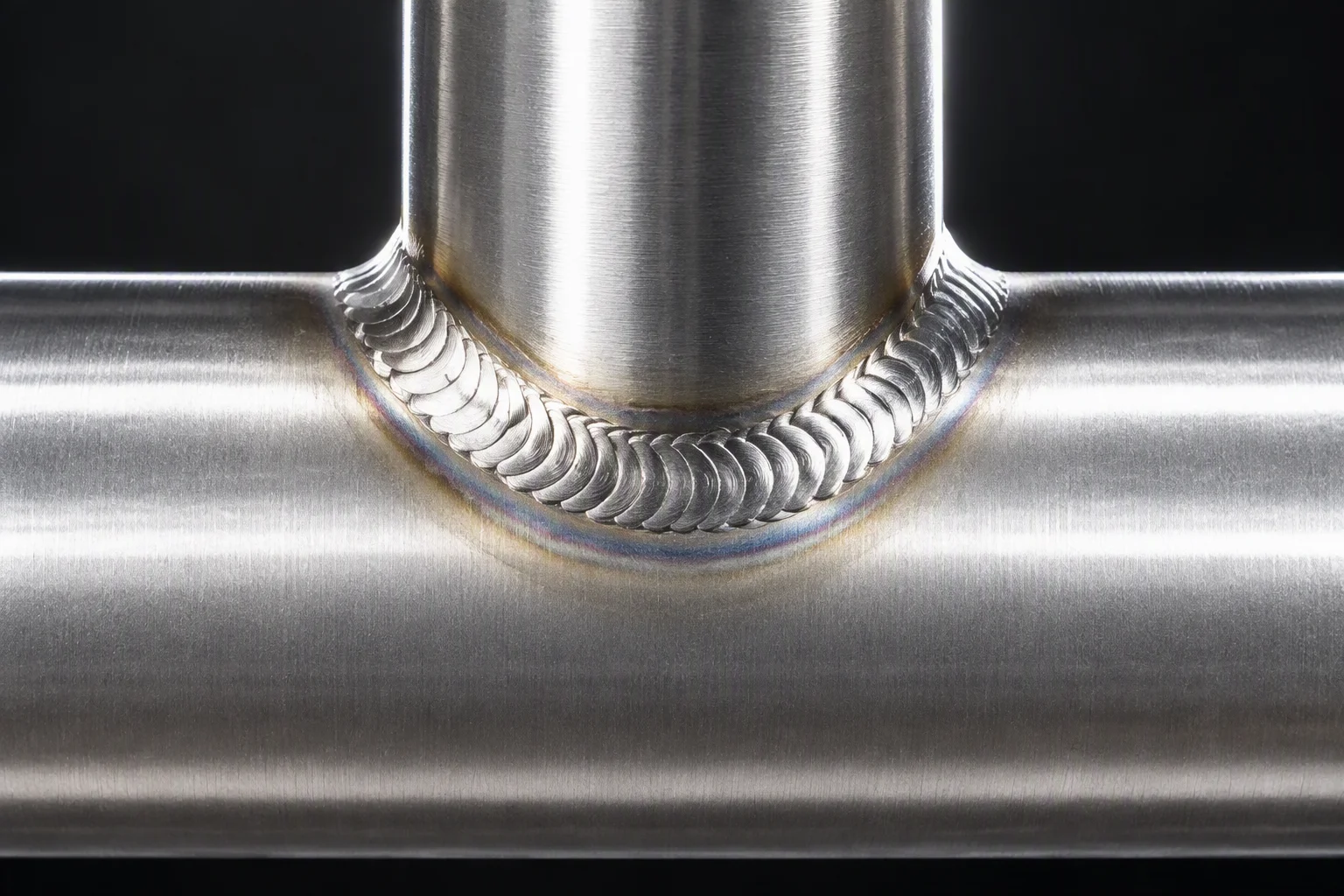
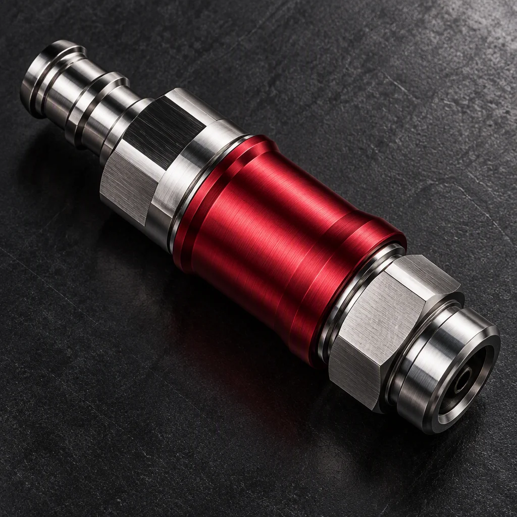
Joint images on this page are technical renderings, not site photography.
Traceable back to the heat
Grade · passivation · heat number
Grade
SUS304 and 316L for wetted parts. industry practice
Internal surface
Passivated after joining, because the inside of a manifold is where the coolant actually lives. industry practice
Heat number
Every assembly carries a heat-number trace back to the bar it was cut from. industry practice
Marking
Traceability runs on the number, not on a legible label. Nothing on this page depends on reading a stamp from a photograph.
Proof, individually
Every assembly · before the cleanroom

- 01
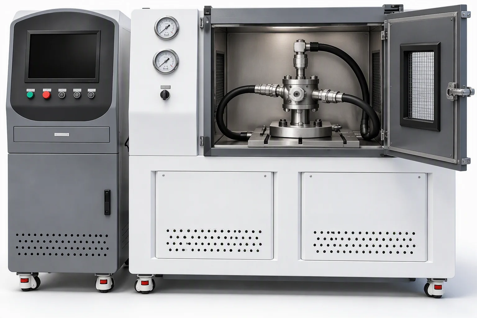
Every welded assembly is proof-tested on its own at ≈1.5× working pressure. industry practice
- 02
Proof runs before the assembly enters the cleanroom. A part that has just held water does not open a clean bay.
- 03
Sampling is the alternative, and sampling is what leaves the untested units in the rack when one fails.
The burst margin
Working pressure · proof · minimum burst
Level 01
Working pressure
100 psi (≈6.9 bar) for the UQD size family · per the OCP UQD specification
Level 02
Proof
≈1.5× working pressure, applied to every welded assembly · industry practice
Level 03
Minimum burst
300 psi for a 100 psi working pressure, i.e. 3× WP · per the OCP UQD specification Rev 1.0
Leak rate and the record of it
Target · filed by serial number
Helium target
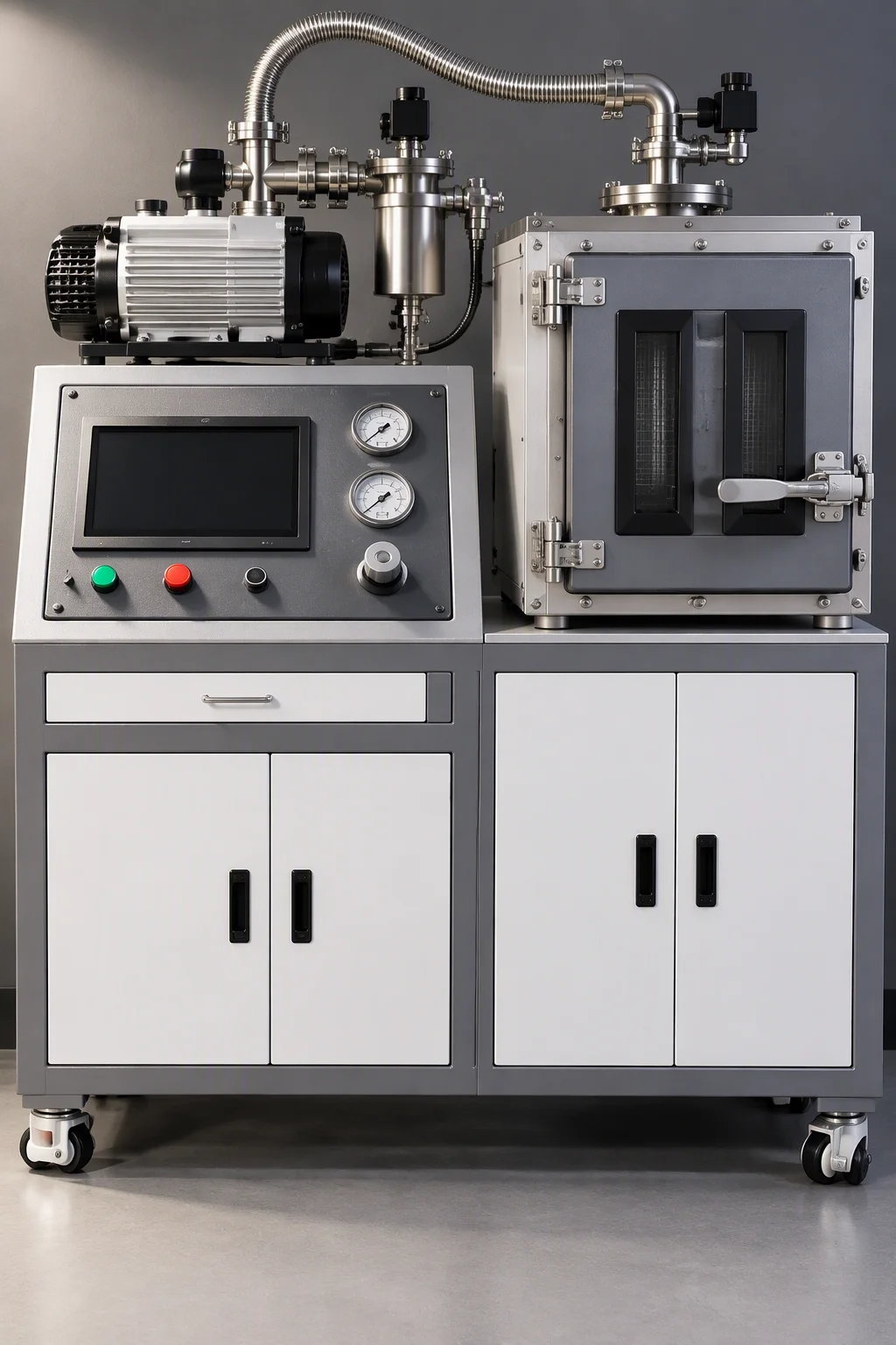
≤1×10⁻⁵ mbar·L/s. industry practice
Weld records
Filed by serial number, not by shift or by batch. process capability
Pressure logs
The proof log travels with the same serial number as the weld record, so the two can be read together. process capability
Why a number
A leak target turns a leak into a measurement, and a measurement can be argued with. Appearance cannot.
When the joint is disputed
Samples · records · welder qualification
Sample archive
Welded samples are archived by batch, so the joint under discussion still exists after the order shipped. process capability
Re-check path
A sample can be re-examined against the inspection report it was accepted under. process capability
Welder records
Qualification records are maintained per welder and per process. process capability
What that buys you
A disagreement about a joint becomes a document lookup instead of a re-manufacture.
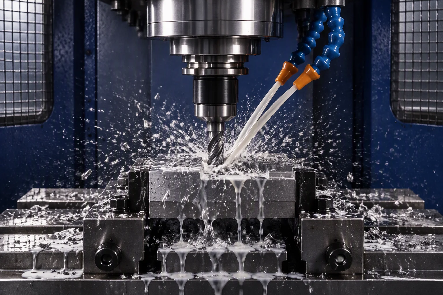
Either side of this station
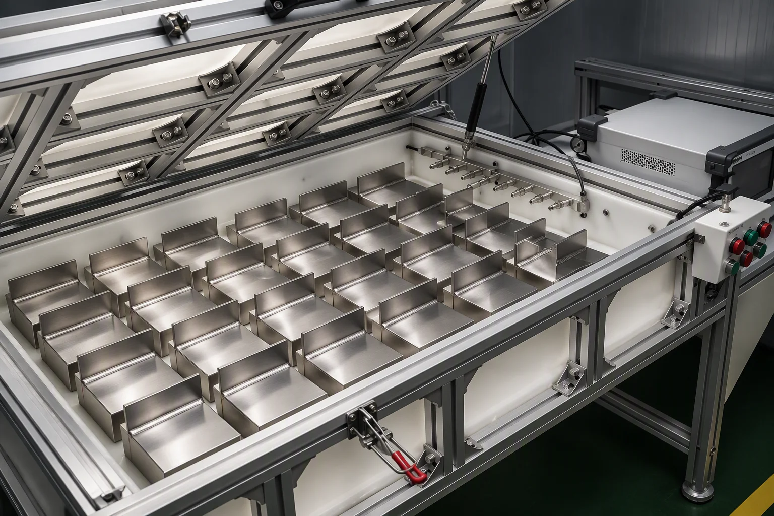
Machining upstream · clean assembly downstream
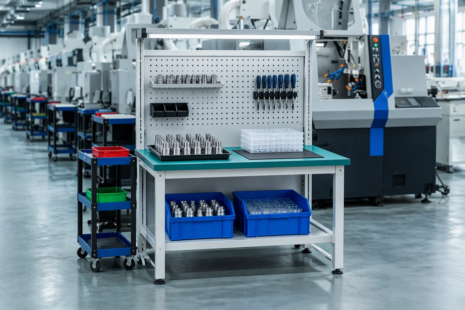
Before and after the joint
Shop frames · not welding bays
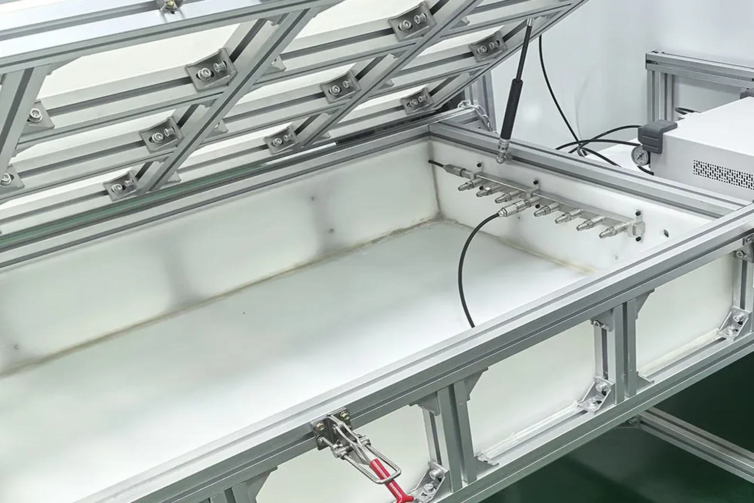
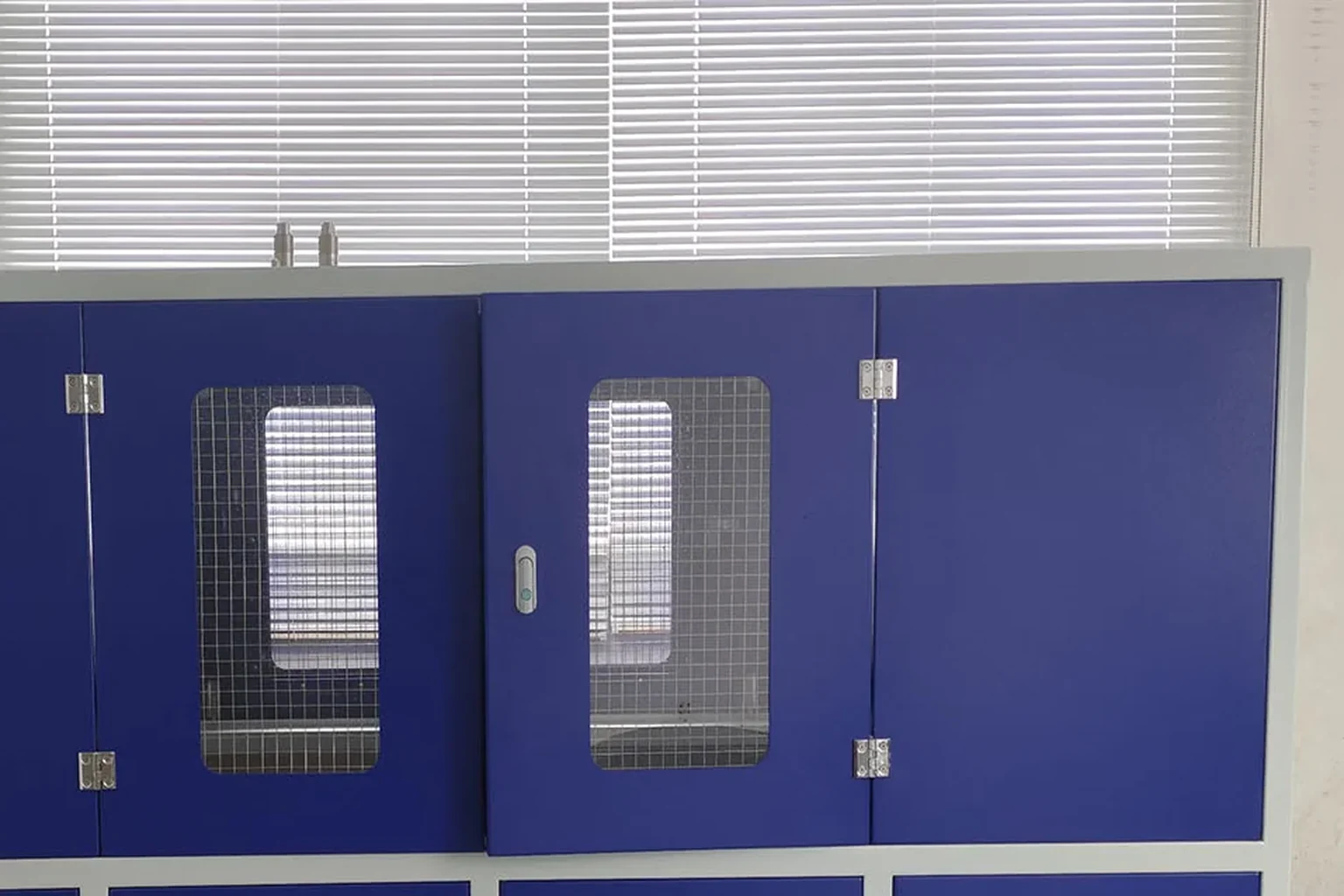
Neither frame is a welding bay: one is a bench rig and one is a cabinet unit, both photographed elsewhere on the shop floor. This batch has no site photography of the welding floor, and no frame on this page is presented as one.

Spec sheet request
What is your working pressure?
Send the assembly type, the working pressure it has to hold and the record you need back. Acceptance is framed against the 3× working pressure burst margin (per the OCP UQD specification Rev 1.0), and the weld samples stay archived either way.
Send the WP One business day · English quote + a one-page spec sheet