
Tolerance note · one subtraction
Budget the chain, not the coupling
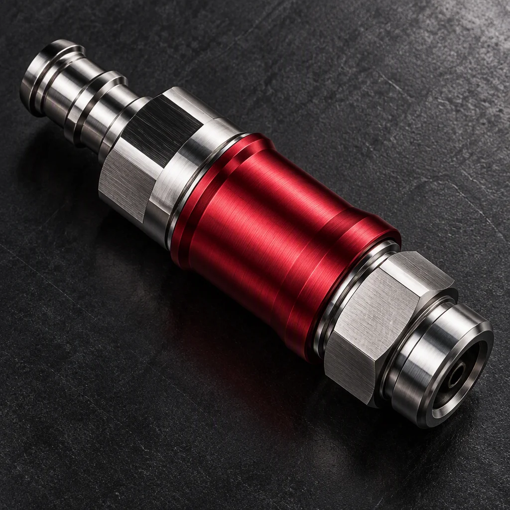
Blind-mate docking is a budget problem — every millimetre belongs to somebody.
Send tray drawings01
Worst case, not typical
A tolerance budget does not ask whether the tray will dock. It asks how much allowance is left at the worst tray position, after every item in the chain has taken its share.
02
One allowance, many claimants
Rack squareness, rail play, mounting deflection after torque and cold-plate flatness all draw on the same allowance. Nothing in that list is free, and nothing in it is somebody else's problem.
03
A ceiling is not a budget
The interface's misalignment tolerance is the largest error it can absorb — a ceiling, not a number to plan against. Planning at the ceiling is how a design passes on paper and fails in the second row.
Three sources on this page: interface capability (industry practice) · the allowance and float the specification sets · the cold-plate interface the specification lists.
Interface, allowance, float, remainder
Capability · allowance · float · what is left
Interface capability
±5 mm radial · ±2.7° angularthe misalignment one class of blind-mate interface is able to absorb. industry practice
Spec allowance (MIS-A)
0.5–1.0 mm radial · 0.5° angularthe misalignment the UQDB specification allows a docking pair to be out by. per the OCP UQDB specification
Float compensation
±1.0 mm radial · ±0.5° angularthe maximum a floating mechanism takes out, and the whole of what it takes out. per the OCP UQDB specification
Left for the machine chain
5 mm − 1.0 mm = 4.0 mm · 2.7° − 0.5° = 2.2°the difference between what the interface can absorb and what the docking pair is allowed to be out by. This is the allowance the rack, tray and mounting chain has to live inside. derived by this note
Capability is an industry figure · allowance and float are set by the specification · the 4.0 mm and 2.2° figures are this note's own subtraction and appear in no standard.
The allowance ceiling (1.0 mm) and the float cap (±1.0 mm) are the same order of magnitude: they cannot be added. Float is the last line of defence, not the main budget.
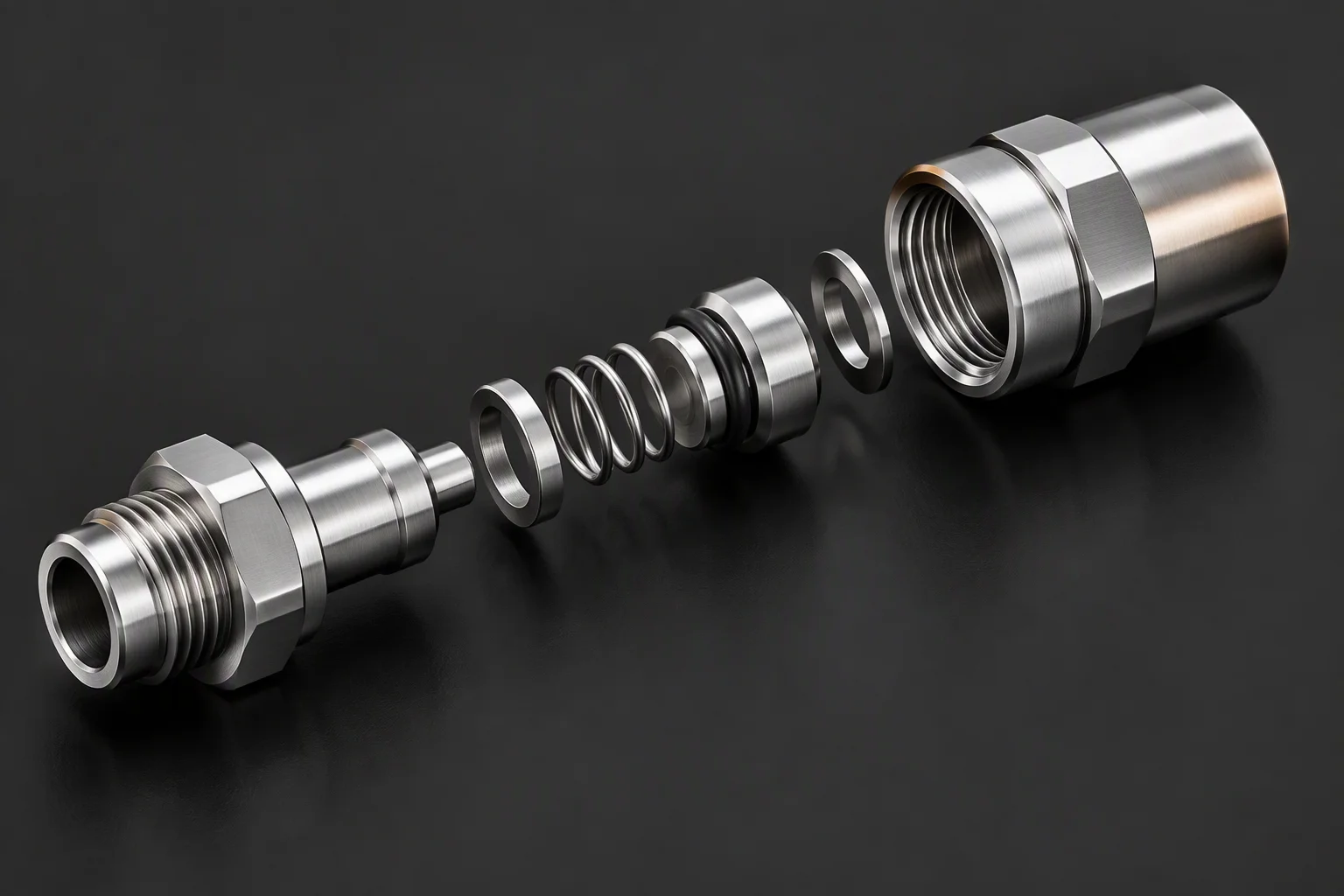
The cold-plate side
Materials · flatness · share of the window
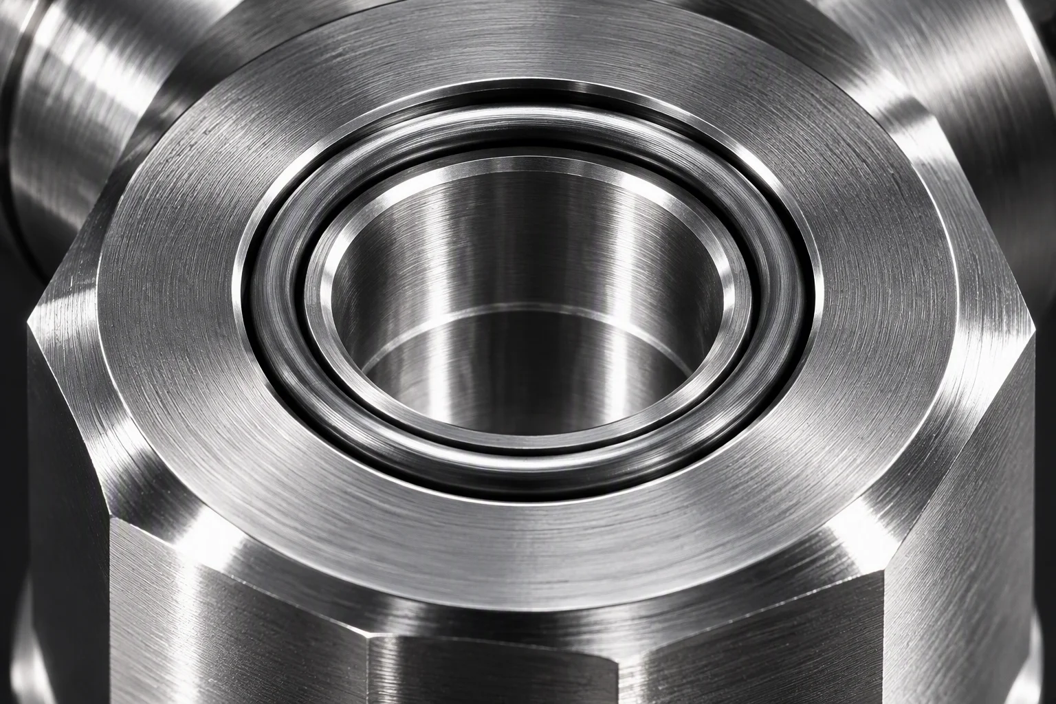
Materials per spec
C11000 · 6061-T6 / T651 · A360the cold-plate materials the specification lists for a docking interface: copper, two aluminium tempers and one cast aluminium. per the OCP UQDB specification
Face flatness, minimum
0.05 mmacross the coupling face. per the OCP UQDB specification
Share of the window
0.05 mm against the 1.0 mm float cap is about 5% of that window. Not a rounding error: it takes a real share and has to be given one. derived by this note
Flatness is a datum defined when the face is machined, not a number measured after the plate has been bolted down. A coupling face that is flat in free state and pulled out of flat by its mounting bolts has already spent its share before the tray moves. Surface quality on that face exists to serve the seal; it is not a finish chosen for appearance.
The 5% figure is this note's division of the two published values. It is not a budget line in any standard.

Splitting the remainder
Rack · rails · mounting · wear
Rack squareness
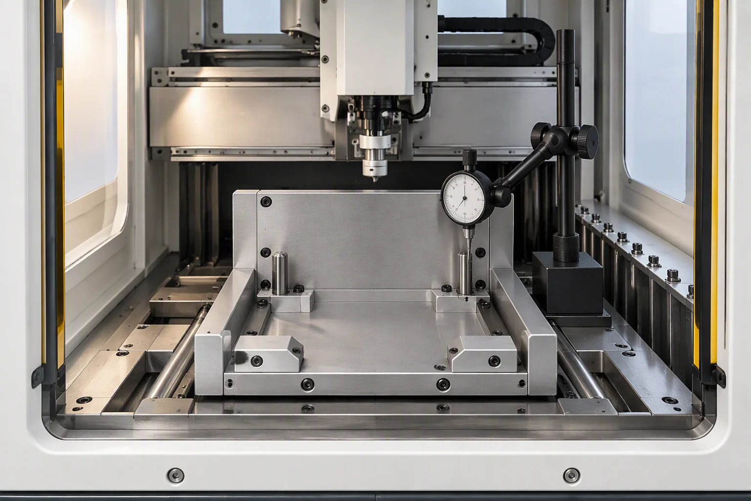
Establish a datum face on the rack first and measure the rest from it. Without a datum, every other item in the chain is being measured from a different origin.
Rail play
The lateral freedom the tray keeps inside its rails is taken straight out of the radial allowance. It is the item most often left out of the budget because it is a clearance rather than a dimension.
Mounting deflection
Where the plate actually sits after the bolts are torqued, not where the drawing puts it. Budget the difference, and check it on the first assembly rather than the tenth.
Wear reserve
Hold a fixed slice back for service wear. A budget that is fully spent at the first build has nowhere left to go after a year of tray swaps.
Only two of these figures are given by the specification — ±1.0 mm / ±0.5° and 0.05 mm. What each item above receives is decided by your structure, and this note does not invent those numbers.
Verifying it before the rack
Fixture · worst position · angular arm · log
01
Fixture first
Prove the docking on a fixture before the tray goes into a rack. The fixture has to reproduce the real rail friction — a smooth guide pin measures a mechanism nobody ships.
02
Worst position
Test the worst tray position: top and bottom of the rack, furthest row. The best position passes in every design, which is why it proves nothing.
03
Angular arm
An angular error becomes displacement only after it is multiplied by the alignment arm — the distance from the tray's locating pin to the plug. A short arm hides angular error; a long one exposes it.
04
Log it
Record the allocation at each design review, then backfill the measured numbers once the first rack is assembled. A budget nobody re-reads after the first build is a document, not a control.
Acceptance reference: the interface class absorbs ±5 mm / ±2.7° (industry practice). Use it as the upper bound of the test, never as the target of the design.
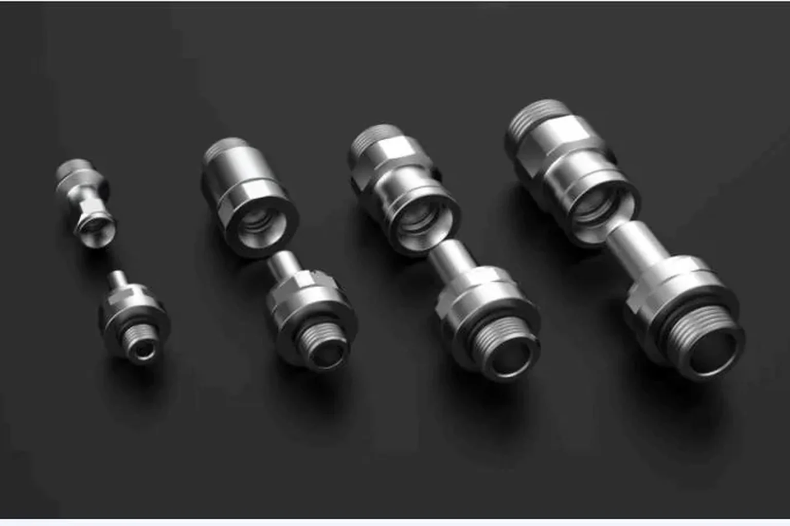
The three grades, and the float between them
UQDB03 · UQDB04 · UQDB06 · float plate

Docking tolerance review
Whose budget is the missing millimetre in?
Send the tray and backplate drawings. The review runs the same subtraction this note runs, and returns the worksheet with the quote rather than as a download.
Request the review One business day · English quote + a one-page spec sheetPublished 2026-09-24 · when a figure in this note changes, the note is rewritten and the change is dated here. The specification values quoted above are reproduced from the published interface standard; the two remaining figures are this note's own subtraction and division.